Hi
I know this is very basic but my toroidal transformer is 220 volt primary and 2 x 25 v secondaries on the label it says the red and yellow secondaries are 25v@4.5 amp and the black and orange are o .
the black and orange have a black dot beside them .
I plugged it in and tested the wires not connected to anything with my vom.
I have 50v from the red and yellow wires and 26v from the black and orange.
I must be doing something wrong here.
This transformer is new out of the box today.
I have searched and found nothing like this anywhere.
Any help here would be greatly appreciated
This for a Zen ,I was going to attach to the rectifier as shown in the Zen schematic.
Also wouldnt 26vx1.414 give me 36.76v not the 34 described in the Zen article. My house supply is 240v.
Any ideas would be a great help.
Thanks
Mark
Hi
I think i found my mistake Ihave measured the voltage difference between the positive and negative secondary wires and it is 28v ,I suppose that is because of the higher input voltage of 240v .
How do I reduce this28v to 24v to gt the right voltage 34v going to the capaciters?
Thanks Mark
I think i found my mistake Ihave measured the voltage difference between the positive and negative secondary wires and it is 28v ,I suppose that is because of the higher input voltage of 240v .
How do I reduce this28v to 24v to gt the right voltage 34v going to the capaciters?
Thanks Mark
The unloaded voltage of most transformers is higher than the spec'd voltage (under load) that you will get once you actually hook this up. IIRC, this is part of the % regulation that is specified for some transformers. You should be fine.
Make sure that you match the correct leads up with one another for each pari of secondaries if you are not using them in parallel.
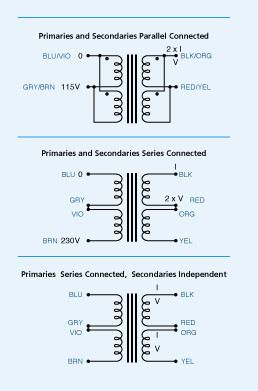
For example, you would use the black and red leads for one secondary and the orange and yellow leads for the other in the drawing above.
Make sure that you match the correct leads up with one another for each pari of secondaries if you are not using them in parallel.
For example, you would use the black and red leads for one secondary and the orange and yellow leads for the other in the drawing above.
mccreamark said:
I have 24.9v and 24.8v dc from each bridge I was expecting 35v?
Does it change when it connected to board ?
Thanks again
Mark
If you attach a capacitor across the bridge output you will see a change.
The voltage is different with and without caps.
One 1000 uF with 50 VDC rating will be enough.
When I design a power amp circuit, I use VAC * 1.33 = VDC. (4/3).
This is a worst case figure for a normal sized trafo, at high power output.
As mentioned, the recitifed DC voltage when trafo is unloaded,
can many times be 1.5 X VAC rating. (3/2)
The bigger transformer in relation to amplifier power,
the less it will drop when heavy loaded.
There are no rules that can tell this exactly. What final DC Voltage levels will be.
It can be very different for different brands of trafos.
hi
I have hooked up my 225 vac transformer to 2 x 63v 10000mf caps and still get 37v dc .I,m using a full wave rectifier.
Also I made a test Zen on a bread board and hooked up to the transformer and fried the r1 resistor.
i also put a 10r power resistor on the power supply to simulate load and fried it before it fried I got 456Ma of current and the dc volts where about .5v.
I know I am doing something dumb but I can,t work it out ,
I`m on my last r1 (Ive ordered more) but I can,t think of why this is happening.
Any ideas would be great.
Thank you
Mark
Hi it was 28v ac from the transformer unconnected.
24.9v ac connected to the bridge
36.9v dc comming out of the bridge
Here are some pictures just in case i,ve done something really dumb.
I connected the 2 pairs secondaries to 2 seperate bridges and then on to 2 10,000mf caps.
Yellow wire is 25v ac Orange is 0
Brown is + Blue - .
I,m getting 36.9v dc at the caps and out of the caps .
The caps have 2 dummy lugs on the anode side i thought they were to secure the cap to the pcb so I didnt connect them.
Everthing is connected by temporary connectors till I get it right.
Thanks
Mark
24.9v ac connected to the bridge
36.9v dc comming out of the bridge
Here are some pictures just in case i,ve done something really dumb.
An externally hosted image should be here but it was not working when we last tested it.
An externally hosted image should be here but it was not working when we last tested it.
An externally hosted image should be here but it was not working when we last tested it.
I connected the 2 pairs secondaries to 2 seperate bridges and then on to 2 10,000mf caps.
Yellow wire is 25v ac Orange is 0
Brown is + Blue - .
I,m getting 36.9v dc at the caps and out of the caps .
The caps have 2 dummy lugs on the anode side i thought they were to secure the cap to the pcb so I didnt connect them.
Everthing is connected by temporary connectors till I get it right.
Thanks
Mark
Hi,
I think your DMV is not accurate on the AC range.
28Vac should give ~38Vdc on the caps.
Why does yours fall to 36.9Vdc? What load is pulling this down by over a volt?
Why does the 28Vac appear to read 24.9Vac when connected to the rectifier?
Have another look at the smoothing caps and convince yourself that the blue is connected to negative terminal.
Hi Andrew ,
you are correct the voltage is 38 v on the caps.
Can I ask you how do i get the 34vdc that NP has on his Zen amp schematic .
I thought if I followed the plans exactly I would get the 34v he got.
I looked at the side of the caps and they show lug2 as the anode and the crimped lug as the neg, but I may be reading it wrong.
Also I just tried to check the current so I hooked up my DVM at the 10A setting ,to the end wires to complete the circuit and got no reading which makes me think something is wrong.
After with the Dthis unplugged from the wall outlet I had 36v across the caps I do have 38v when plugged in.
I also checked AC volts and got 80v ac across the caps which worries me.
checked
I think you need to test the output of this power supply under
a load. Once you put it under a load like the ZEN will draw the
voltage will be a little lower probably 2 or 3v lower in fact. You
might try a light bulb as a test load if you don't have a big power
resistor. But that voltage is not that critical I wouldn't worry about it. The 36v you measure across the cap with the power
off is simply the stored charge and will stay there a long time
if you don't have a bleeder resistor.
About measuring amprige: you connect the leads in seriese
with a load it sort of sounded like you tried to measure the
currrent across the dc lines if you did you probably blew the
fuse.
Hi Nordic,
No filter
just the transformer connected to theIEC plug with fuse.
IEC plug ground, grounded to the chassis.
Then the secondaries to rectifier ,rectifier to the caps and the caps
to the pcb .
I think my power supply is OK I am just taking too many incorrect readings.
Thanks
Mark
No filter
just the transformer connected to theIEC plug with fuse.
IEC plug ground, grounded to the chassis.
Then the secondaries to rectifier ,rectifier to the caps and the caps
to the pcb .
I think my power supply is OK I am just taking too many incorrect readings.
Thanks
Mark
- Status
- This old topic is closed. If you want to reopen this topic, contact a moderator using the "Report Post" button.
- Home
- Amplifiers
- Pass Labs
- Transformer