you have such a nice instrument.
I wish i could have one.
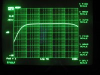
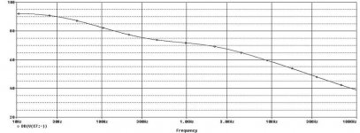
Anyways out of my PSpice Analyzer (ehehe sounds just like your Agilent analyzer) i get this frequency response...as the total freq resp MM + MC.
The two curves totally look the same to me...look at the file.
Ad far as this is concern it would look like the inverse RIAA i am using is not correct.
I wish i could have one.
Anyways out of my PSpice Analyzer (ehehe sounds just like your Agilent analyzer) i get this frequency response...as the total freq resp MM + MC.
The two curves totally look the same to me...look at the file.
Ad far as this is concern it would look like the inverse RIAA i am using is not correct.
Attachments
analog_sa said:
There is a -40db attenuation from the inverse riaa.
Stefano
Not sure what driving impedance the inverse riaa expects but it's unlikely to be 150ohm. You may need to modify the 1.91k resistor respectively.
thanks a lot for your adive.
I tried to change the output resistor from 150ohm to 1.9K with no effect and tried to change the 1.91K in series at the capacitor on the inverse RIAA block but the odd point on the middle band was just magnified.
Did i miss something?
Did you mean to change something else?
Thank you
Thermistor causing grief
I think there is a good explanation about why thermistors may be causing you grief.
Remember from the early notes that what the thermistors do is change the bias point. As soon as the thermistors start to do their thing they will increase distortion.
The distortion plots from Pasos today show thatthe distortion is really low. But if the device is running hot, the thermistor action won't lower the distortion. If the thermistor is doing its thing, increasing bias will cause increasing heat which will cause the thermistor to operate, which will increase distortion.
I'll bet the transistors are running hotter than folks think. Remember Papa's note saying that he sets bias with a thermometer. He gradually turns up bias until the MOSFET temp is 25degrees C above ambient. Check that before you give up on thermistors.
Anybody got a candy thermometer? Anybody want to make s'mores over their class A amp? I'll bring the graham crackers.
I think there is a good explanation about why thermistors may be causing you grief.
Remember from the early notes that what the thermistors do is change the bias point. As soon as the thermistors start to do their thing they will increase distortion.
The distortion plots from Pasos today show thatthe distortion is really low. But if the device is running hot, the thermistor action won't lower the distortion. If the thermistor is doing its thing, increasing bias will cause increasing heat which will cause the thermistor to operate, which will increase distortion.
I'll bet the transistors are running hotter than folks think.
Remember Papa's note saying that he sets bias with a thermometer. He gradually turns up bias until the MOSFET temp is 25degrees C above ambient. Check that before you give up on thermistors.Anybody got a candy thermometer? Anybody want to make s'mores over their class A amp? I'll bring the graham crackers.
The question of whether to use a balanced or single-ended RIAA stage is an old one. There are arguments for both sides of the issue but, lacking a center tap on the coils in the phono cartridge, you're left creating a virtual ground between the two existing pins. Whether this is truly a balanced signal is in the eye of the beholder.
Note that you can't just build a balanced phono stage and hot-wire the two existing signal pins to the + and - inputs of the balanced circuit--if you do, you'll get a ferocious hum. You have to supply a new wiring harness from the phono stage to the arm and shield both the signal leads.
Most people don't even try. The vast majority of phono circuits on the market are single-ended. Not surprisingly, turntables are wired to mate with those phono stages. Those who wish to try balanced phono stages are left having to create their own wiring harness or buy one of the few on the market. There are a few commercial products that allow balanced phono inputs, but you'll see instructions on how to roll your own interconnects in the owner's manuals.
I've seen posts wherein people claimed they were learning things from simulation programs. I've also seen posts where it was painfully clear that the poster hadn't learned anything at all. I suppose it depends on how you define the word 'learn.' I've yet to see a program that actually teaches things like Norton's Law and Thevenin equivalents and such. About the most you can hope for is to enter a circuit and see if it works. But--and this seems to be the case here--there are circuits that work and simulations claim they don't (see the first part of the Aleph-X thread for more of same). Is it the simulation program? Is it the device models? Is it the operator? Or perhaps it was just cosmic rays hitting the processor chip in your computer at the wrong moment, causing odd results.
If you want to build a circuit, then build the circuit. That way you can actually listen to music.
Grey
GRollins said:The question of whether to use a balanced or single-ended RIAA stage is an old one. There are arguments for both sides of the issue but, lacking a center tap on the coils in the phono cartridge, you're left creating a virtual ground between the two existing pins. Whether this is truly a balanced signal is in the eye of the beholder.
Note that you can't just build a balanced phono stage and hot-wire the two existing signal pins to the + and - inputs of the balanced circuit--if you do, you'll get a ferocious hum. You have to supply a new wiring harness from the phono stage to the arm and shield both the signal leads.
Most people don't even try. The vast majority of phono circuits on the market are single-ended. Not surprisingly, turntables are wired to mate with those phono stages. Those who wish to try balanced phono stages are left having to create their own wiring harness or buy one of the few on the market. There are a few commercial products that allow balanced phono inputs, but you'll see instructions on how to roll your own interconnects in the owner's manuals.
I've seen posts wherein people claimed they were learning things from simulation programs. I've also seen posts where it was painfully clear that the poster hadn't learned anything at all. I suppose it depends on how you define the word 'learn.' I've yet to see a program that actually teaches things like Norton's Law and Thevenin equivalents and such. About the most you can hope for is to enter a circuit and see if it works. But--and this seems to be the case here--there are circuits that work and simulations claim they don't (see the first part of the Aleph-X thread for more of same). Is it the simulation program? Is it the device models? Is it the operator? Or perhaps it was just cosmic rays hitting the processor chip in your computer at the wrong moment, causing odd results.
If you want to build a circuit, then build the circuit. That way you can actually listen to music.
Grey
Grey, besides the fact you don't like simulators which i still think are useful for the purpose they are made for,nothing more nothing less and, as you can see...in this fortunated case....frequency response obtained by Spice looks the same as the one obtained by direct measuring of the circuit.
Surprisingly in this case simulator is not so horrible, isn't it?
It is also not always possible to own an agilent analyzer...for poor guy as i am..
")
Said that, since your experience goes far beyond mine plus the simulator together for sure, don't you wanna comment the graphs posted here on the 3d?
Hi Stefano
Two possible issues:
1. The Hagerman inverse riaa expects 50ohm of source and you have 150ohm. Reduce 1k91 to 1k8
2. Not sure what is the capacitance in parallel to 88.7k in your circuit. Not enough resolution for my ageing eyes. Should be 2n7 in parallel with 33n and it looks like 27n.
In fact you can check this riaa in the feedback of any opamp, no need to be this complicated discrete circuit and results will be the same.
Thank you very much analog.
Your eyes are in a perfect shape
I just changed the value and now the inverse curve response show a deviation from the ideal response of 0.08dB which is in accordance with the original specification.
Now the cure response at the output of the inverse RIAA filter is exacly like the response tortello kindly posted on a previous 3d....not too bad for such a stupid tool (i mean spice...eheheh not the agilent...magaaarriiii!!)
thank you again you were very nice to help me out.
Stefanoo said:
Grey, besides the fact you don't like simulators which i still think are useful for the purpose they are made for,nothing more nothing less and, as you can see...in this fortunated case....frequency response obtained by Spice looks the same as the one obtained by direct measuring of the circuit.
Surprisingly in this case simulator is not so horrible, isn't it?
It is also not always possible to own an agilent analyzer...for poor guy as i am..
Said that, since your experience goes far beyond mine plus the simulator together for sure, don't you wanna comment the graphs posted here on the 3d?
And what did you 'learn' from the simulation? Nothing. The RIAA curve is easily found on the web, so the shape of it shouldn't be a surprise. Did you learn that Nelson's RIAA circuit was wrong? No. Did you learn that the circuit works as designed? Well, yes, but anyone could have told you that ahead of time. Or you should have realized it yourself. Me, I'd rather have spent that time building a circuit I could listen to rather than wasting it on simulations that accomplish nothing.
Hint: If you've got a proven circuit's schematic in hand--and I think Nelson's stuff qualifies--you can probably build it and expect it to function properly.
You'd have to have a pretty screwy RIAA EQ not to come up with a curve that will 'totally look the same' as an RIAA curve. The devil, as always, is in the details. The curve is basically a 6dB/oct low pass with a flattened spot in the middle. But getting it right...that's another matter, entirely.
I don't have an Agilent either, but it doesn't stop me from measuring RIAA accuracy. I don't like RIAA networks as test bench stuff because then you're faced with the errors in the bench network as well as the errors in the phono stage.
True story: Carver put out a preamp a while back. The preamp had a phono stage (optional) but also had a passive re-emphasis circuit. The idea being that the user could put their CD player into the EQ circuit, then into the phono stage and see if they preferred the 'colorations' of the phono stage over the 'flat' CD input. The punchline of the joke was that the two RIAA circuits did not sum to flat response. So which one was at fault, the emphasis or de-emphasis curve? Or were they both wrong? (If memory serves, the phono stage was fairly close but the little CD-emphasis dingus was way off. Draw your own conclusions.)
Phooey!
Measure the phono response directly. Spreadsheets are freely available on the web that show proper RIAA response down to zillionths of a dB. Start at 20Hz and watch the response fall. If it deviates from the proper response, you'll be able to tell.
And you won't have to worry about all this silly loading stuff...
Or, as people have said repeatedly...do your homework, please.
Grey
well thank you for your answer.
Nevertheless i don't fully agree with you.
Just becase you don't like/use simulators doesn't mean that they are useless.
In fact i have learned by simulation that a small variation of a specific capacitor incides on the middle band and specifically on lack of middle band thus distortion.
Obviously i have a proven circuit as you said and that's a given.
But knowing how the things varies by variating some of the paramenters i think it is important/interesting as well.
This brought to my attention the fact that capacitors need to be accurately matched and of selected values.
Unfortunately we are not in school anymore and asking something doesn't necessary mean to not do homeworks as well, but thanks anyways for the good point you brought up.
Stefanoo said:
In fact i have learned by simulation that a small variation of a specific capacitor incides on the middle band and specifically on lack of middle band thus distortion.
Actually, if you have to have a simulator show you that changing the value of a capacitor in a low pass filter changes the response of the filter it's a pretty clear demonstration that you haven't thought things through. Simulations are not a substitute for thinking--though many treat them as such.
Randomly changing component values in a filter--any filter--always changes the response. You can change the values, but only as long as you maintain the same time constants. This isn't something I'd suggest until you've pondered the what and why of a filter for a while. Those values were not simply plucked out of thin air.
So, no, I don't think you learned anything by simulating the circuit.
The RIAA filter exists because it cuts down on the low end transit required by the cutter head. This reduces the power needed when cutting the master, allows for more music to be placed on an album side, and makes it easier for the playback cartridge to track the music. It's not a win-win proposition, however. By boosting the low end on playback, it increases rumble and woofer excursion caused by warped records.
It would be nice if a filter wasn't needed, but there's not a practical way to record (or play back) albums without it, even now. In fact, there's not a signal medium (short of playing music live, and even that tends to involve filters of one sort or another, though it doesn't have to) that doesn't require a filter of some sort:
--Records: RIAA filter. (at least two variants exist, and historically there were other filters before the RIAA)
--Tape: Any of several filters, depending on the era, tape heads, etc. (You want to get kinky? Go back to wire recorders.)
--Radio: It doesn't even bear thinking about. There are filters of one sort or another all through tuners, not to mention a 19kHz filter in some models.
--CD: The infamous "brick wall" filter at 22kHz...'nuff said...
And so on...
Tinker with the values of the filters at your peril. They're there for a reason. You shouldn't need someone or something (e.g. a simulation) to point out the obvious: Changing things changes things.
Grey
 OT and rules-breaking posts removed. Discuss filters, not each others shortcomings.
- Status
- This old topic is closed. If you want to reopen this topic, contact a moderator using the "Report Post" button.
- Home
- Amplifiers
- Pass Labs
- Some questions on (X)-ONO