We already did it here.
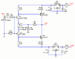
Now we can take it one step further by avoiding the output cap (just C1 stays as a small coupling cap between stages, so it can be of high quality and still not expensive).
Four PSs seems a lot but it's two actually: we start with +24V(V2) and -12V(V5). Then we regulate them down: +24V to +12V(V4) and -12V to -3.3V(V1).
Gain is 10dB (since you like it LOUD).
For clarity, schematic doesn't show bypass/decoupling caps - 10uF Low ESR on every rail will do the job, but depending on PS type,you can try whatever you like (RC combos, small caps in parallel, etc...).
The pot/volume control at input is not shown but 10 to 20K log device is recommended.
Yup. I remember it. IF i can solder the little farts without frying 50% of them, I will try a couple different iterations. Schematic above added to the queue. THanks Juma for the ideas.
Juma,
This seems a bit back to front but I wondered if there is a simple way to make this idea work well ...
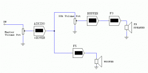
I want to drive both F3 and F5 in parallel out of the Aikido preamp ( O/P Z of about 500R) and if use the BF862 gain stage to raise the gain of the F5 to exceed the gain of the F3, where would it be possible to fit a volume trimmer - the F3 feeds a 97dB/W FR driver and the F5 into a 96dB/W bass driver (speaker uses a biamp or split passive Xover)
Juma,
Got parts coming for two different versions of an integrated F5 for the PC desk. Will try cascode bf862 with lm337/317 regulators stepping down the voltage and one with Jfet, Bipolar combo. All SMD Parts. Hope to keep it small and tight. Well see. Haven't decide on output devices. Being for nearfield, I may use either TO220 Toshibas or standard FQA. What do you think about possibility of lateral output? I know gain is low, but I do love that lateral sound.
Got parts coming for two different versions of an integrated F5 for the PC desk. Will try cascode bf862 with lm337/317 regulators stepping down the voltage and one with Jfet, Bipolar combo. All SMD Parts. Hope to keep it small and tight. Well see. Haven't decide on output devices. Being for nearfield, I may use either TO220 Toshibas or standard FQA. What do you think about possibility of lateral output? I know gain is low, but I do love that lateral sound.
Not the best idea. Output devices in F5 work in common Source mode i.e. as voltage amplifier. Laterals don't have enough gm for that job. I tried it and wasn't satisfied. IMHO 2sk2013/2sj313 are the best option....What do you think about possibility of lateral output? ...
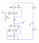
If you want Laterals in smal PC desk amp, use them as Source Followers - I like the one in attachment. R4 sets the BS170's Id at about 15mA and R6 will set the Laterals' Id - 0.5A was OK for me. The gain equals R8/R10. This little amp gives 9V_peak of clean swing at 4 Ohm load.
EDIT:
you can leave the R5 out if you plan to drive it with B1 in the same case. B1's output cap is not needed too.
Attachments
Last edited:
Not the best idea. Output devices in F5 work in common Source mode i.e. as voltage amplifier. Laterals don't have enough gm for that job. I tried it and wasn't satisfied. IMHO 2sk2013/2sj313 are the best option.
If you want Laterals in smal PC desk amp, use them as Source Followers - I like the one in attachment. R4 sets the BS170's Id at about 15mA and R6 will set the Laterals' Id - 0.5A was OK for me. The gain equals R8/R10. This little amp gives 9V_peak of clean swing at 4 Ohm load.
SRPP FE. I like it. Can swing big voltage into high impedance load, correct. Missing gate resistors for input fets? I need to stop talking to you. Can't keep up. Thanks.
Last edited:
Never.... Missing gate resistors for input fets? ...
Behold the R3 and R10 - they are gate resistors too, although you are used to smaller values...
Not the best idea. Output devices in F5 work in common Source mode i.e. as voltage amplifier. Laterals don't have enough gm for that job. I tried it and wasn't satisfied. IMHO 2sk2013/2sj313 are the best option.
If you want Laterals in smal PC desk amp, use them as Source Followers - I like the one in attachment. R4 sets the BS170's Id at about 15mA and R6 will set the Laterals' Id - 0.5A was OK for me. The gain equals R8/R10. This little amp gives 9V_peak of clean swing at 4 Ohm load.
EDIT:
you can leave the R5 out if you plan to drive it with B1 in the same case. B1's output cap is not needed too.
Juma,
Got boards made and parts for both the gain version in post#5? using BTJ output as well as the cascoded buffer pre. Looking to do something similar to one above as well and have a question. What is the second 100K resistor, the one that is tied to input, for? Why not jsut tie the first 100K to ground. I am not acutally going to do this circuit( 1014D SRPP instead), but just looking and trying to understand.
This little amp gives 9V_peak of clean swing at 4 Ohm load..
Juma, can you put your name and the created date in your schematics? That will be useful for those who collect circuits
OK Juma,
The 100K resistors sets the input impedance and if driving from B1, it is not needed because of high output impedance of said device. You say the 12K resistor sets the Id of the BS170(thought BS portion was joke at first ) at about 15mA. I see that the source of the bottom BS is grounded, so how does the 12K resistors affect bias? Does it sink some of the feedback voltage, creating a Vref of sorts?
The 100K resistors sets the input impedance and if driving from B1, it is not needed because of high output impedance of said device. You say the 12K resistor sets the Id of the BS170(thought BS portion was joke at first
did you mean to type that?................. if driving from B1, it is not needed because of high output impedance of said device..................
If so, what does the post mean?
Juma,
Got boards made and parts for both the gain version in post#5? using BTJ output as well as the cascoded buffer pre. Looking to do something similar to one above as well and have a question. What is the second 100K resistor, the one that is tied to input, for? Why not jsut tie the first 100K to ground. I am not acutally going to do this circuit( 1014D SRPP instead), but just looking and trying to understand.
Sorry, but I realy don't get it...
I'm doing many things during the day and I can not know or remember what you think about at certain moment.
Please refer the exact question to exact post number. Make your questions clear and short and the quality of the answers will improve instantly. Always validate your question from the others guy perspective - you surely know what you mean, but the other guy doesn't (until you make it plain to see)...
Generally, the JFET needs DC path (through resistor) to the GND in order to define Gate's potential.
If you have a coupling cap it will be charged during the operation and it needs to be discharged (through resistor) if you want to avoid unpleasant transients.
Last edited:
Sorry, but I realy don't get it...What's "#5?" Which "cascoded buffer pre" ...
I'm doing many things during the day and I can not know or remember what you think about at certain moment.
Please refer the exact question to exact post number. Make your questions clear and short and the quality of the answers will improve instantly. Always validate your question from the others guy perspective - you surely know what you mean, but the other guy doesn't (until you make it plain to see)...
@Andrew,
Dyslexia kicked in. I mean't low Zo.
Sorry Juma, Forgot the exact post #. I believe it is 53. Included in first pic.
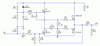
THe cascoded buffer is the BF862 operated in the Low Vds regino with stiff J310 cascode. Pic #2.
Generally, the JFET needs DC path (through resistor) to the GND in order to define Gate's potential.
If you have a coupling cap it will be charged during the operation and it needs to be discharged (through resistor) if you want to avoid unpleasant transients
Wasn't unsure if placement at feedback point intersection changed general bias considerations. So, is it correct to assume that if both the Gate and Source are grounded, does this mean that it being operated at Idss, which happens to be 15mA.
Attachments
Last edited:
- Status
- This old topic is closed. If you want to reopen this topic, contact a moderator using the "Report Post" button.
- Home
- Amplifiers
- Pass Labs
- Preamp ideas for F5


