the quest is for:
in general, understanding of heatsink selection; and
in specific, minimum heatsink limitations for the Zen v4 amp.
here are my calcs.
given:
the zen amp 'idles' at 2A. being totally new to this, i'm not certain what 'idle' means. anyway i'm assuming the transistors each have 2A running through them.
voltage across Q1 = 22v.
voltage across Q2 = 19.34v.
voltage across Q5 = 8v.
the wattage at each Q is therefore:
Q1 = 44W.
Q2 = 38.68W.
Q5 = 16W.
at a temperature rise of 30°C (recommended by Mr. Pass in his project writeup), each Q will need to have heatsinking at the following ratings, not to exceed:
Q1 = 0.68°C/W
Q2 = 0.78°C/W
Q5 = 1.88°C/W
-----------
as an aside, using a more conservative 25°C rise gives the following max ratings:
Q1 = 0.57°C/W
Q2 = 0.64°C/W
Q5 = 1.65°C/W
-----------
because this is a project guided by economics i want the most heatsink/dollar. to date the best i've found is this $30 extrusion at MECI, which has the properties shown here at aavid thermalloy.
the total Rth for that extrusion at 24.75" is 0.28°C/W. i plugged in a few alternate lengths for that profile on aavid's worksheet:
1" = 1.39°C/W
2" = 0.96°C/W
3" = 0.80°C/W
4" = 0.69°C/W
5" = 0.62°C/W
6" = 0.57°C/W
so, the following lengths of extrusion could work for the components, individually:
Q1 = 4.125"
Q2 = 3.25"
Q5 = 1"
total length = 8.375" for one channel. assuming i can use the heatsink as a continuous piece, with the components simply spaced apart according to their required lengths, there ought to be plenty of extrusion to fit 2 channels on a single heatsink.
-------
(even using the 24° rise figures, the required lengths still work: Q1 = 6", Q2 = 5", Q5 = 1"; total = 12".)
-------
so, the big question is, does it work well enough to have components spaced apart?
i think i'm willing to give it a try. if i'm totally barking up the wrong tree, perhaps someone will point out the error of my ways. otherwise, well maybe i'll burn through a few FET's.
plus, i think there's great 'cool factor' potential (pun, haha) - an amp design with a single long extrusion will be interesting...
at the very least, i hope this will help other fellow newbies who may be trying to get a handle on the economics of heatsinking.
/andrew - now tries to think of a way to explain a 25" hunk of metal in the living room to the wife...
till said:hmm. one heatsink 85*150*250 mm each channel works well at 2 Ampere Bias.
good to hear...the extrusion i'm looking at is 80*178*629...pretty comparable.
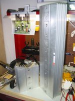
Using the 24" MECI heatsink vertically is not supposed to be very efficient according to Rod Elliot's heat sink article. There's an Zen on passdiy that has that configuration and the builder notes that even with two 24" heatsinks, it is still very hot.
You might be better off slicing them up into 8" tall pieces or around there and setting them side by side. I plan to do this. They are actually 24.75" long so you could get three 8" or four 6" pieces out of it very easily.
If you don't have a saw big enough to cut it, you could rent a 14" chop saw from Home Depot. Using an abrasive blade will take a little while as I found with my 12" DeWalt but it will do it. I've since moved to a Freud LU89M012 per PDaniel's recommendation.
Also, if you don't have these heatsinks already, you should know that the back is not completely flat. There are four machined pads 2.25" wide and I estimate between 1/32" and 1/64" deep.
You could tie these together using copper bar from http://www.onlinemetals.com or simply angle aluminum.
Here's a picture of an 8" piece I cut and the uncut piece next to it.
Attachments
faustian bargin said:the quest is for:
in general, understanding of heatsink selection; and
in specific, minimum heatsink limitations for the Zen v4 amp.
here are my calcs.
given:
the zen amp 'idles' at 2A. being totally new to this, i'm not certain what 'idle' means. anyway i'm assuming the transistors each have 2A running through them.
voltage across Q1 = 22v.
voltage across Q2 = 19.34v.
voltage across Q5 = 8v.
the wattage at each Q is therefore:
Q1 = 44W.
Q2 = 38.68W.
Q5 = 16W.
-- snip --
/andrew - now tries to think of a way to explain a 25" hunk of metal in the living room to the wife...
Only Q1 and Q2 carry that high current. You have noticed that they will dissipate about the same power and the total power is the supply voltage times the current which is 42 times a little more than 2 A which is close to 90 W and the article states 100 W so we use that number. For the others transistors you don't have to worry. For those 100 W you want the 30 degree increase which gives you 0.3 K/W heatsink for one channel. If you wish you may split that into 2 (or more providing you join them well thermally) pieces at 0.6 K/W. You cannot take a 0.6 K/W heatsink and double the length and use that as suggested. The pieces need to be separate and side by side, not on top of eachother. As you have stated the total is 0.28 K/W for the WHOLE extrusion and that is about what you need for one channel. But as you also stated it is 0.57 for a 6 inch piece so cutting the 24 inches into 4 equal pieces and using them side by side gets you 0.14 K/W instead of the whole length 0.28. That is how you should use it - 4 pieces side by side (e.g. 2 mono blocks or a big stereo amp with two pieces each side).
ultrachrome said:Using the 24" MECI heatsink vertically is not supposed to be very efficient according to Rod Elliot's heat sink article. There's an Zen on passdiy that has that configuration and the builder notes that even with two 24" heatsinks, it is still very hot.
....
If you don't have a saw big enough to cut it, you could rent a 14" chop saw from Home Depot.
....
ah. well, there's my answer. if i can't get what i need from an uncut 24.75" extrusion, then it will probably be more cost-effective for me to use 4 of the 5.25" pieces (which perform at 0.60°C/W) MECI is selling for $9.95 each. if i wanted to cut the longer one, i'd have to rent a saw, and the cost of that would be more than the difference.
That's a good point. I spent about $80 on a blade to cut those heatsinks but since I plan to use it for other things and it gives me the flexibility to use the heatsinks the way I want to, I decided it was worth it.
Sometimes I wonder if I am buying so much equipment to build my amps that I could have just saved myself the effort and bought a nice production amp. But then I remind myself that I would then miss out on half the fun.
Even still, I have to justify every tool purchase. I don't want to end up with a garage full of tools that I don't use.
François said:I am planning to use the same trick (4 pieces of 9'' section for each channel). I will put one transistor on each piece. The fourth piece will be unused (no transistor on it).
Did you get that batch of heatsinks you were talking about on the trading post?
dave
No  I lost the bid and I forgot to update the previous thread. I have now to use the same heatsink they are talking here. I have a 6 feet bar that I will cut into 8 pieces of 9''. I am now wondering if I can use longer wire to mount all the transistor on a separate section of the heatsink. It may be overkill but safe.
I lost the bid and I forgot to update the previous thread. I have now to use the same heatsink they are talking here. I have a 6 feet bar that I will cut into 8 pieces of 9''. I am now wondering if I can use longer wire to mount all the transistor on a separate section of the heatsink. It may be overkill but safe.François said:I am planning to use the same trick (4 pieces of 9'' section for each channel). I will put one transistor on each piece. The fourth piece will be unused (no transistor on it).
You're not allowed to do that!
It's against policy here to use (valuable) heatsinks for cosmetic purposes only.
heatsinks calc.
Hi Francois, I got this heatsinks too and I was wondering how to connect the transistors, my thinking is to use wire too if there is not problem in doing that. What kind of wire we can use(already order some silver teflon) and what gauge has to be.Also if you have some inputs on how to built the chassis will be apreciated. thanks in advance.
Hi Francois, I got this heatsinks too and I was wondering how to connect the transistors, my thinking is to use wire too if there is not problem in doing that. What kind of wire we can use(already order some silver teflon) and what gauge has to be.Also if you have some inputs on how to built the chassis will be apreciated. thanks in advance.
Re: heatsinks calc.
I will cut my heatsink in 8 parts of 9''. Each set of 4 heatsinks will be joined together with aluminum (L shape). One for the top and one for the bottom. If this is not enough strong, I will add solid aluminum bar in the middle. The transistor will be mounted directly on the heatsink. I will also probably put an aluminum bar over the transistor to ensure they are perfectly touching the heatsink.
I am not sure. Maybe other people can answer. I don't think silver plated wire are necessary. heavy gauge copper wire should be perfect.porfi4ever said:Hi Francois, I got this heatsinks too and I was wondering how to connect the transistors, my thinking is to use wire too if there is not problem in doing that. What kind of wire we can use(already order some silver teflon) and what gauge has to be.
Also if you have some inputs on how to built the chassis will be apreciated. thanks in advance.
I will cut my heatsink in 8 parts of 9''. Each set of 4 heatsinks will be joined together with aluminum (L shape). One for the top and one for the bottom. If this is not enough strong, I will add solid aluminum bar in the middle. The transistor will be mounted directly on the heatsink. I will also probably put an aluminum bar over the transistor to ensure they are perfectly touching the heatsink.
faustian bargin said:
ah. well, there's my answer. if i can't get what i need from an uncut 24.75" extrusion, then it will probably be more cost-effective for me to use 4 of the 5.25" pieces (which perform at 0.60°C/W) MECI is selling for $9.95 each. if i wanted to cut the longer one, i'd have to rent a saw, and the cost of that would be more than the difference.
So would 4 of these $9.95 MECI heatsinks (I'm assuming 2/channel) be enough for the Zen IV? Does anyone have any experience with how good these heat sinks are?
Cheers,
Dave
well, i hope so because i just bought 4 of them. besides, MECI sold out of the long pieces months ago.
if my calculations jive with the real world, i think it should work fine putting (for one channel) Q1 on one sink, while Q2 and Q5 share the other.
someday i might actually build it.
/andrew
**edit - PS: nice 8 month resurrection by the way i wonder what the record is for bringing old threads back to life...
if my calculations jive with the real world, i think it should work fine putting (for one channel) Q1 on one sink, while Q2 and Q5 share the other.
someday i might actually build it.
/andrew
**edit - PS: nice 8 month resurrection by the way
i wonder what the record is for bringing old threads back to life...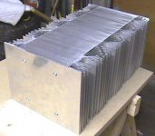
François,
I am in the building stage of my Zen V4 and am surprised by your experience that 8 x 9" sections of that particular extrusion isn't enough for two channels. I was planning to use 4 x 6" sections for two channels. I performed a test where I solidly clamped two 50 watt resistors to one 6" section and ran 80 W through them (the back was milled flat). The heat sink temperature, after an hour, was hot to the touch, but I could keep my hand on the heat sink for several seconds. The ambient air temperature was about 20C.
When you measured the temperature, did you raise your amp a couple inches off the bench to allow free air flow to the base of the heat sinks?
Jeremy
Yes, the amp was raised about 1 inch from the floor. I was surprised too, I though my heat sink was overkill. This thing is huge and weights more than 50 pounds (with components). After one hour of listenning, I can keep my hand on the heat sink for only a few seconds (let say 5-6). I'll try to post another picture this evening with the transistors assembly.
François,
I just took a closer look at your ZV4. By the way, thanks for the pictures on your web site. It appears that your heat sink extrusions are quite a bit smaller than the MECI extrusions I and, apparently, faustian bargin are using. The MECI extrusions are about 3" deep and 7" wide (and a couple more fins). Yours appear to be 2" deep and 5" wide. Is this correct?
Jeremy
- Status
- This old topic is closed. If you want to reopen this topic, contact a moderator using the "Report Post" button.
- Home
- Amplifiers
- Pass Labs
- my heatsink calcs for Zen v4