Nice work but have to tied 230 V wires together with others? Not got for safety reasons but not good either of you want to have low noise. I recommend that you try to have 230 stuff with low voltage stuff.And we are done!
Started listening to it and still am! The detail and headroom is incredible
No hum, no nothingjust beautifull music
Thanks to all of you who helped me along the way! Ofcourse a big thanks to Mr. Nelson
Merry Christmas to all of you and a very happy new year!

High vs low voltage
Hi PA,
Thank you!
But I don't quite understand what you mean.
I did not ty any 230V lines to low voltage lines.... that's good I think?
Nice work but have to tied 230 V wires together with others? Not got for safety reasons but not good either of you want to have low noise. I recommend that you try to have 230 stuff with low voltage stuff.
Hi PA,
Thank you!
But I don't quite understand what you mean.
I did not ty any 230V lines to low voltage lines.... that's good I think?
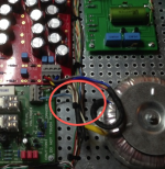
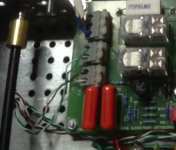
The small wires at the left are quite dangerous! They must be 230 volt wires since you have ALL stuff on the soft start connected to the mains. This is really dangerous to have those thin wires through those holes with sharp edges! You know, I write about this in big black letters about this safety issue. It's also printed in block letters on the pcb. YOU MUST FIX THIS!
Attachments
Last edited:
Wires
Hi P-A,
Those thin wires are only the switch and LED wires, so they have very little voltage. They do not go through holes in the chassis. No danger there.
The other thing about the softstart close to the low voltage side, that is the case and I will follow up on that. Thanks for the tip!
NB: All "thin" wires are low voltage wires(exept for the lead in thin ones of the toroid offcourse) and they do not go through holes of any kind. That was the case before, but I changed it a while ago.
The small wires at the left are quite dangerous! They must be 230 volt wires since you have ALL stuff on the soft start connected to the mains.
Hi P-A,
Those thin wires are only the switch and LED wires, so they have very little voltage. They do not go through holes in the chassis. No danger there.
The other thing about the softstart close to the low voltage side, that is the case and I will follow up on that. Thanks for the tip!
NB: All "thin" wires are low voltage wires(exept for the lead in thin ones of the toroid offcourse) and they do not go through holes of any kind. That was the case before, but I changed it a while ago.
No..... EVERYTHING is at 230 Volt potential!!! Lethal! Why don't take a voltmeter and measure?Hi P-A,
Those thin wires are only the switch and LED wires, so they have very little voltage.
You must have 8 mm creapage distance between mains side and secondary side.P-A,
I could raise the softstart about 5cm...... that would provide a bit more distance. Would that be enough or do you think I should revise the layout?
Thanks!
B1 Buffer with 2sk170GR?
I know this question has been asked, but I can't find a concise answer (if there is, and I missed it, I apologize and kindly ask for a link) :
Can 4 matched GR grade 170's, with an IDSS lower than Nelson's minimum recommended value of 5mA be used without issue?
Thank you to everyone who is able to provide some insight.
I know this question has been asked, but I can't find a concise answer
(if there is, and I missed it, I apologize and kindly ask for a link) :Can 4 matched GR grade 170's, with an IDSS lower than Nelson's minimum recommended value of 5mA be used without issue?
Thank you to everyone who is able to provide some insight.
The B1 is essentially a SE ended ClassA amplifier with a gain of just a tiny fraction less than 1. I have found that a cascade of 5 of these B1 loses about 4% of the signal level. That makes the gain of a B1 ~ 0.99 (-0.1dB)
A single ended ClassA amplifier has a maximum output current in the opposite direction of the supply polarity of just a fraction less than the bias current.
If you use an 8mA Idss device and bias it at 8mA, then the maximum output current is ~-7.9mApk to your load.
If you use an 4mA Idss device and bias it at 4mA, then the maximum output current is ~-3.9mApk to your load.
OK I'm completely new to all this and have never attempted anything like it in 60+ years. I've looked this project a number of times but every time 'till now courage and PCB stock have been in inverse supply. Now at last I have Mr Pass's board to hand, and have Mundorf caps and Audio Note resistors on their way.
But the attenuator value is driving me nuts.
I have trawled though all the hundreds of pages of this thread and can’t see any guide, other than to try a few different values and see what works. I was hoping to go with something like the Goldpoint mini-v so I would really like to get it close first up
My valve mono blocks have an input impedance of 100K Ohms
The Slee Reflex M phono (+Grado Ref Sonata) gives “Output impedance (driving impedance): 1k Ohm (will drive 10k Ohms and above)”
I can’t find the output for the Cayin 17A CDP (output 2.3v?) but a direct connection between player and power blocks would blow out the windows. I normally run the cdp at about half the volume phono. I use chord anthem interconnects (1 metre).
My inclination is to the 20K (Special) Goldpoint Mini-v but only because it is at a pretty good price at the moment and my completely ignorant guess is that I should pitch lower rather than higher.
There is also quality in the one from JAC Music in Germany very well priced but it seems to be only in 47K. Is that too much?
Any help, suggestions or recommendations gratefully received.
22K is the recommended maximum from Salas for the DCB1 I'm going to use a 25K pot, as I thought that was the upper limit I had seen posted at some point. 20K sounds like a good choice
I'm currently doing a verro board DCB1. Hopefully won't be too long before it is finished!
Tony.
I'm currently doing a verro board DCB1. Hopefully won't be too long before it is finished!
Tony.
Thanks.
25k was the value used by Mr Pass in the original diagram and commentary. I became a little concerned when my 100K power amp input seemed to be at least twice that of other examples given. Where I have been able to find inputs for retail Pass amps they seem to give an input of 30/20K so was this in the thinking of the creator when he chose 25K? That's roughly 1:1; so should I be looking at 100K?
I thought I saw something somewhere about a 1:10 ratio which is why I was thinking 10-20K.
But I could have dreamt that. It's been on my mind a lot lately.
David
The B1 is essentially a SE ended ClassA amplifier with a gain of just a tiny fraction less than 1. I have found that a cascade of 5 of these B1 loses about 4% of the signal level. That makes the gain of a B1 ~ 0.99 (-0.1dB)
A single ended ClassA amplifier has a maximum output current in the opposite direction of the supply polarity of just a fraction less than the bias current.
If you use an 8mA Idss device and bias it at 8mA, then the maximum output current is ~-7.9mApk to your load.
If you use an 4mA Idss device and bias it at 4mA, then the maximum output current is ~-3.9mApk to your load.
But only if distortion does not matter.
A peak signal current about 10% off the IDSS is acceptable, then the distortion increases.
But only if distortion does not matter.
A peak signal current about 10% off the IDSS is acceptable, then the distortion increases.
Monotonically so in B1's case. Expect 0.003% at 2V RMS on test gear HighZ load.
- Home
- Amplifiers
- Pass Labs
- B1 Buffer Preamp