Funny I did suspect the PSU earlier
#3438
What kind of PSU are you using ?
Some will not like the high inrush current of C1.
Either try substituting C1 with a smaller say 1000uF cap or try the series resistor as I have mentioned.
C2 is not such a problem because is has R2 in series with it.
There probably isn't anything wrong with the PSU, that particular one just doesn't like a highly capacitive load.
Andy
Hi.
The psu is detailed a few posts above - standard LM317T implementation. Post 3474.
Well yesterday I tried it with the 100R in place of the 1R. No likey! This is without C1 in place too. I haven't tried a 1000uF cap there so could quickly solder one in and recheck.
Altered the R2 resistor by the LM317T to get 20V instead of 24V. Didn't improve anything. This thing just doesnt seem to like being loaded! This evening I'll try it with the different load resistors as you/Andrew have suggested.
Cheers,
John
Last edited:
The LM317 MUST HAVE >3V across it to work.
Are you sure 1) The LM317 is OK and 2) The circuit is correct and 3) There is at least 24V at its input.
You must also have the 0.1uF at the input and 1uF at the output as close to the LM317 as practical.
With the huge C1 of the B1 you must also use the two protection diodes across the LM317, failure to use these will result in failure of the device. Failure may not occur immediately but is due to the Load (ie C1) trying to operate the LM317 in reverse.
The LM317 MUST HAVE >3V across it to work.
Are you sure 1) The LM317 is OK and 2) The circuit is correct and 3) There is at least 24V at its input.
You must also have the 0.1uF at the input and 1uF at the output as close to the LM317 as practical.
With the huge C1 of the B1 you must also use the two protection diodes across the LM317, failure to use these will result in failure of the device.
Andrew/Andy - Yes - Approx. 24V before the rectifiers. 29-30V after. It's just a textbook implementation of the simplest LM317T circuit, with a 1000uF/50 cap after the rectifiers, and a 1000uF cap after the reg. 1uF (in National's dastasheet it says either 0.1uF film cap or 1uF tantalum) tantalum caps at the input/output right next to the 317 legs. 10uF cap across R2, which sets the output voltage to reduce ripple further, again according to the datasheet. Pin outs all correct. I HAVEN'T added the diodes but I wouldn't have thought that would hurt as most leave them out anyways, and 6L6 (posted his link a page back) used the same PSU board and setup as myself with no problems. However he may have used a different brand of LM317T (mine's ST). I think the finger of blame must point towards the 317 really - it just doesn't seem to want to perform when connected to a load, but measures the correct voltage when unloaded. I have another PSU here I can use which I'm going to setup later, but the curious side of myself would love to know what's wrong with it all the same.
http://www.diyaudio.com/forums/audio-sector/149672-universal-power-supply-pcb.html
Last edited:
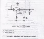
The National Semiconductor Datasheet says you must use the diodes.
Especially as C1 is 15000uF.
It'll be interesting to see if it works with a resistive load.
True, but I've seen others using high values without the diodes to no ill effect (I believe Naim use a huge 15000uF / 63V cap after with the LM317T in their Hicap too). Plus in my build I would have thought the 1000uF directly after the reg would have eased the inrush from the 10,000uF (not 15,000uF in my case) C1 on my B1?
I've also tried the PSU without C1 and it still won't work.
I'll see what happens with a resistive load later today (fingers crossed) and perhaps that will shed some light on it.
Noted Andrew - it was advice I actually read on here aeons back, but it obviously has resulted in a damaged LM317T. Lesson learned.
Have subbed in another PSU I had (for a Creek phono stage) and it's working beautifully, and sounding rather nice too! Very pleased indeed")
Busy for the next few days but going to build another LM317T PSU - have ordered some 1N4002 diodes to play it safe this time.
Back to some music listening! Thank you for all the help today chaps.
- John
Have subbed in another PSU I had (for a Creek phono stage) and it's working beautifully, and sounding rather nice too! Very pleased indeed
Busy for the next few days but going to build another LM317T PSU - have ordered some 1N4002 diodes to play it safe this time.
Back to some music listening! Thank you for all the help today chaps.
- John
When you get around to it, try a Salas Shunt Reg you will be amazed at the difference that that will make.
You can buy the DCB1 board at DIYAUDIO.com and just use the Regulator end of it.
Its not expensive and really makes a big difference.
I made my own PCB, its that easy. The Europe shop is out of stock but the US shop will supply at about £18.00 (incl P&P).
I did build the DCB1 but stayed with my B1 in the end. I had the spare DCB1 PCB but that was quickly snapped up when I offered it for sale with all the components.
You can view the result at Post #3405 in this thread, together with the LM317 version in the following Post #3406.
Last edited:
Sound interesting - I actually have an unused DCB1 'Mezmerize' board but would rather have something a little smaller, especially if I'm only going to use the shunt reg. part of it anyways. Do you have the URL of the UK shop perchance Andy? Cheers.
Will check out that post now.
Will check out that post now.
When you get around to it, try a Salas Shunt Reg you will be amazed at the difference that that will make.
You can buy the DCB1 board at DIYAUDIO.com and just use the Regulator end of it.
Its not expensive and really makes a big difference.
I made my own PCB, its that easy. The Europe shop is out of stock but the US shop will supply at about £18.00 (incl P&P).
I did build the DCB1 but stayed with my B1 in the end. I had the spare DCB1 PCB but that was quickly snapped up when I offered it for sale with all the components.
You can view the result at Post #3405 in this thread, together with the LM317 version in the following Post #3406.
Bit confused here Andy - you said below you couldn't hear a difference betwen the shunt reg and the LM317 version? Have I missed a post?
- John
- John
Personally I couldn't hear any difference between the Salas Dual Reg and the LM317 Reg running at 22V.
Do you reckon there might be any benefit in building the single Shunt Reg supply over the Dual Reg ?
The photo is the previous incarnation with the LM317.
Its at the top of this page - go to STORE.
I made that quote before listening to it for a long time. The lower impedance of the PSU does brighten up the sound stage, BUT, you wont hear it immediately.
The biggest improvement for me was gouing from a Capacitive Multiplier PSU to the LM317.
Others will disagree and swear by the C.M.
The B1 is pretyy tolerant of any PSU - except your faulty one.
Last edited:
What I'm trying to say is for about £50 give it a try. I did and I'm now stuck on the Salas Reg even if I am still playing with it.
I get you. Sometimes you don't really notice an improvement until you've taken it out of your system. Had that a few times over the years with various 'mods'.
Didn't realise there was a store here now - great! Will check that out shortly (and here I was saying I was going to kick the DIY habit after the B1....
)Cheers,
- John
As the IRFPs aren't matched you are chasing good with bad.
All you are after is a single regulated supply.
As I stayed with the B1 and not the DCB1 the match of +Vcc and -Vcc was irrelevant.
If you want to mod the supply to a single +VREG - I found it easier to use it as it was and not worry about +Vcc and -Vcc.
Also with the four MOS-FETs its easier to get rid of the heat.
I've got two spare 2E heatsinks (used) if you want to PM me.
I'll probably breadboard a single-rail shunt reg - the Mezmerize board I have is really too big to fit into my current enclosure, and it'd be a bit of a waste to only use the shunt reg section of it.
Thanks for the offer of the heatsinks, but I have plenty of spares, and I'd probably use a 4mm thick copper base for a heatsink in this instance.
Cheers,
- John
Thanks for the offer of the heatsinks, but I have plenty of spares, and I'd probably use a 4mm thick copper base for a heatsink in this instance.
Cheers,
- John
The Salas doesnt need matched JFets. just try to get them about the 10mA mark for the LEDs.
The LEDs dont need to be closely matched either just measure their Vf and get four strings that are as close as you can get them. I just bought 300 x 3mm LEDs on E-Bay for £10.
Fortunately I bought some matched JFETS and LEDs for a Mezmerize group buy on here a couple years back - ideal for this PSU as I won't be using the Mezmerize board now. This B1 sounds good enough as it is, and that's with a pretty pedestrian PSU
Had another go with the PSU yesterday. Removed the 'old' LM317T and replaced it with a new one (I'd ordered a pair via Ebay). Had the same problem again - measured fine unloaded. But loaded the voltage just dropped to virtually nothing. This was with the protection diodes in place too.
Order some from a different seller. Still 'ST' brand. Arrived this morning - looked a little different from the first two. Different font used on the case, and (what looks like) ST etched into the body over the ST print. This one worked first time - spot on 22v. No sagging under load.
I can only assume the first two I got were either fakes, or I was unlucky enough to have gotten a couple from a bad batch. I'm assuming it's the former.
B1 is up and running and sounding fantastic - thanks for everyone's help, plus Mr Pass of course for designing such a great buffer. Lots of happy hours listening ahead I think
Cheers,
- John
P.S. Markings on the (potentially) fake/bad LM317T are:
LM317T
CC0T7 VW
MAR 1015
The 'funny' thing is, the one that I have now which works LOOKS fake (slightly blurry font/print) and the faulty pair both have pin sharp print & a more 'sharply' molded case/body...
Last edited:
- Home
- Amplifiers
- Pass Labs
- B1 Buffer Preamp