")
Why do you use dual supplies if you can`t get rid of the input and output capacitors anyway?
With the single supply the capacitors will be biased by the voltage present at the the input and output, this is an advantage according to some people.
Please correct me if I am wrong.
Why do you use dual supplies if you can`t get rid of the input and output capacitors anyway?
my power amps are mono amps
and I will use a 4-pole input selector
have had several of these C-core trafos for years
and I would like to use them
power supply does get bigger
and it ain't cheaper either
but I like the simpler connections to buffer/LDR curcuit
and maybe consider that its 'almost' like a 4-box preamp
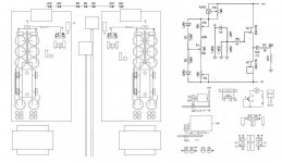
Attachments
my power amps are mono amps
and I will use a 4-pole input selector
have had several of these C-core trafos for years
and I would like to use them
power supply does get bigger
and it ain't cheaper either
but I like the simpler connections to buffer/LDR curcuit
and maybe consider that its 'almost' like a 4-box preamp
Ok, then I understand
ok
tho trying not to complicate it, I'm now thinking if there could be another pair of jfets
driving optional output
through a simple attenuator, back panel mounted
he, might be best to make it work first
Why not duplicate the circuit you have and wire it in parallel.
Why not duplicate the circuit you have and wire it in parallel.
yeah, I thought about it
but that exsta output may be only slightly attenuated
not a favourite of LDR's
I don't know yet how it will be used
woofers, subs, or maybe a tweeter
would it be better to take signal from LDR, instead of after first buffer ?
or maybe that's what you are saying ?
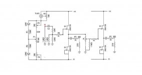
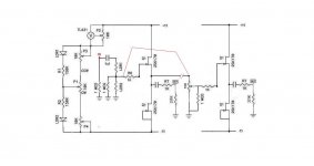
Attachments
Hi, sorry if this has been covered but I haven't managed to make it through the whole thread yet and I'm impatient.
I'm working on a stock B1 and I'd like to go with 3 inputs, one of which is a 3.5mm jack on the front panel for an ipod, laptop, or whatever. This would mean combining the signal grounds for left and right at the jack. Will the B1 tolerate that or will I let the magic smoke out?
Thanks,
Ray
I'm working on a stock B1 and I'd like to go with 3 inputs, one of which is a 3.5mm jack on the front panel for an ipod, laptop, or whatever. This would mean combining the signal grounds for left and right at the jack. Will the B1 tolerate that or will I let the magic smoke out?
Thanks,
Ray
........one of which is a 3.5mm jack on the front panel for an ipod, laptop, or whatever.
This would mean combining the signal grounds for left and right at the jack. Will the B1 tolerate that or will I let the magic smoke out?
Thanks,
Ray
hey, Ray
I guess its stereo, so your jack plug would have left and right signal
you may notice a black plastic ring on the plug pin, which seperates left and right channel
tip and ring are signal. Sleeve (the long plain part of the plug) is always the ground. These plugs and sockets are referred to as TRS and can be used for balanced signals (two signals and a ground) as well.your jack plug would have left and right signal
you may notice a black plastic ring on the plug pin, which seperates left and right channel
I'm jumping ahead of myself (I'm only up to page 55 - three years old) but need to put in an order for some parts. Is the 2sk170 still a good choice or should I be looking for something else. I plan to go with split rails (power brick for a supply).
I run a bi-amp'd system with an 11dB gain difference between the amps so I'll need to add a second section with gain (should I stick with the 2sk170 for the gain section).
I need the B2!!
Thanks and sorry for not reading through before posting questions.
I run a bi-amp'd system with an 11dB gain difference between the amps so I'll need to add a second section with gain (should I stick with the 2sk170 for the gain section).
I need the B2!!
Thanks and sorry for not reading through before posting questions.
Hello , I am new in the forum.After finishing Aleph-x project perfectly ,
I have finished my B1 buffer preamp and it runs well.
I want to use XLR input and output instead of RCA'S in one B1 Board.
I have already checked previous entries for XLR connections but there are only examples for 2 x B1 PCB boards.
Is there any possible solution to convert from RCA to XLR in and out.
I will not use RCAs if there is solution for XLR's, one input channel will also be enough.
Thanks Nelson for your quick respone,
Sorry my english , may be I didn't explained well..
I am working with your orginal B1 PCB board and there are only 2 x RCA inputs and 1x RCA output..
My question ; is it possible to use with 3 pole XLR input and output connectors in current layout of B1 PCB board
(which needs pin 1 for ground/screen , pin2 for positive signal and for pin3 negative signal)
Pin1 and pin 2 are ok but for pin 3 which is negative signal which I struggled to solve, any suggestion or not possible with the current design.
I'm planning to build a balanced version of B1, and I'm gathering some components now. In the original schedule (Passdiy.com) some high quality film caps are required (C100, C200: 1uF and C101, C102: 10uF). I wonder if I could substitute the 1uF by a 3,3uF, and the 10uF by a 22 uF or a 33uF? I have laying around some Jantzen Audio Silver Z-cap (3,3uF) and Clarity Cap SA (22uF and 33uF). Mr. Pass mentions that they can be substituted by other values. Would there be any sonic implications?
A balanced impedance connection must have the impedances balanced (matched) both at the transmit end and at the receive end. The B1 input will be the receive end. All the components that determine it's input impedance MUST be matched to a an accuracy you have determined is adequate for your use. This includes the Capacitor loading.
The output of the B1 is the transmit end. The resistor on the output dominates the send impedance, you can probably get away with matching the output resistor only and use nominal +-5% components for all the others.
The output of the B1 is the transmit end. The resistor on the output dominates the send impedance, you can probably get away with matching the output resistor only and use nominal +-5% components for all the others.
- Home
- Amplifiers
- Pass Labs
- B1 Buffer Preamp