Well thank you Mr Pass.
Just received my board, arrived in 1 week.
Looks great, cant wait to start loading.
If anybody has any tips or links they want to post my way feel free, I may have missed a few.
LSLDR clone next on the mod list around FEB sometime.
Cheers again Nelson
Dean
Just received my board, arrived in 1 week.
Looks great, cant wait to start loading.
If anybody has any tips or links they want to post my way feel free, I may have missed a few.
LSLDR clone next on the mod list around FEB sometime.
Cheers again Nelson
Dean
It's 1/3 smaller than the value specified. Try to find a 15000uf. You may use a bigger voltage rating - 35v.
Jim, thanks for your insights.
i tried to look at some others but 35v-elco's do not fit my PCB, at least not the one i can get @ RS Components webshop.
Do you agree with the following:
"For C1 and C2 I used Digikey P6890-ND. The value is not critical, and you can use as low as 1,000 uF at 25V" source
So, it may be 1/3 smaller then 15.000uF but its still about ten times the specified minimum value. A couple of builders used values in the 1000-15000 range like 1000, 4700, 6800, 8200, 10.000.
That Panasonic cap would work just fine. Try to feed the B1 with at least a half-decent supply and you're OK.
Thanks.
18VDC laptop supply should do the trick.
another DUtch builder used de TREAD from Tangentsoft
Tangent Regulator, Adjustable, plus Diode bridge
An externally hosted image should be here but it was not working when we last tested it.
No more PCB's for sale, but that shouldn't be a problem for the most of you lot
")
Just received my board, arrived in 1 week.
Looks great, cant wait to start loading.
Happy soldering Dean!!!
I must say that I did not read the B1 manual as well as I should. That capacitor is not as critical as I thought. Use whatever you can find that will fit.
If you were to use an unregulated 'wall-wart' power supply, that capacitor would be more important to help smooth and quiet the incoming voltage. A regulated supply like you have shown is going to be quieter, making the extra capacitance not as important. A switch-mode power supply (a laptop supply, like you mentioned) should also be quiet.
If you were to use an unregulated 'wall-wart' power supply, that capacitor would be more important to help smooth and quiet the incoming voltage. A regulated supply like you have shown is going to be quieter, making the extra capacitance not as important. A switch-mode power supply (a laptop supply, like you mentioned) should also be quiet.
I must say that I did not read the B1 manual as well as I should. That capacitor is not as critical as I thought. Use whatever you can find that will fit.
If you were to use an unregulated 'wall-wart' power supply, that capacitor would be more important to help smooth and quiet the incoming voltage. A regulated supply like you have shown is going to be quieter, making the extra capacitance not as important. A switch-mode power supply (a laptop supply, like you mentioned) should also be quiet.
or inject to the signal some high frequency riples,harmonics,noise and god knows what else that is probably not importand to digital circuits ...you need to think this over
50-60hz noises are by far easier to reject in psu design than higher freq poroduced issues
There is no doubt that linear supplies are preferred in audio.
Switchers used in audio by established companies are very engineered and designed to be quiet in the circuit. However, the average switcher that can be bought today is very different from one of 10 years ago.
That said, regardless of input, it would be preferable to have C1 as close to the specified 15000uf as convenient.
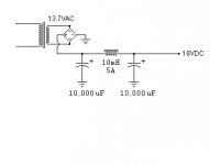
CLC unregulated Power Supply
In the article Mr. Pass recommends a regulated PS. I haven't had any complaints about the really cheap wall wart I've been using since I built mine a couple years ago.
I recently tried this one with some spare parts and some test leads, it sounds very nice. I got the idea from the ZCA here: DIY Class-A 2SK1058 MOSFET Amplifier Project
Attachments
Tolerance-question on resistors
Heey guys,
how important is the tolerance of the resistors. That digikey BOM shows metalfilm resistors with 1% tolerance.
Can is use 5% tolerance?
Or should i then switch to carbon resistors with 1% (or lower), with the "risc" of sounding a bit warmer then metalfilm, which might not be a big problem because the B1 will be connected to a neutral 400watt UcD amp.
Last edited:
.....and offcourse another question
Pass says:
Pass says:
"C3, C100 AND C200 are 1 uF metallized polypropylene film capacitors (Digikey BC2076-ND) C101 and C201 are 10 uF polyester film capacitors (I used Axon 10 uF metallized polypropylene from Orca Design). Feel free to use any comparable types."
Why does the Digikey-BOM show a different C100 and C200 then the above mentioned BC2076-ND?
Can C3 be switched to the exact same 1 uF used in C100 and C200?
Can a 100Vdc be used instead of 63Vdc?
Can a 100Vdc be used instead of 63Vdc?
i have difficulties understanding why that digikey-BOM sometimes show other items of values then B1 manual. Example : all BOM-resistors are 0.5 watt instead of the specified 0.25watt. Quite confusing sometimes for those with less knowledge unfortunately.
Last edited:
In the article Mr. Pass recommends a regulated PS. I haven't had any complaints about the really cheap wall wart I've been using since I built mine a couple years ago.
I recently tried this one with some spare parts and some test leads, it sounds very nice. I got the idea from the ZCA here: DIY Class-A 2SK1058 MOSFET Amplifier Project
I hope you did not buy a 5A inductor.
The stereo B1 consumes ~20mA
No, they were all my parts box. What I've found so far says that the inductor should be rated for 20% more current than it is expected to draw. Does that sound reasonable?
It would be a lot cheaper than a 5 Amp one.
Heey guys,
how important is the tolerance of the resistors. That digikey BOM shows metalfilm resistors with 1% tolerance.
Can is use 5% tolerance?
Or should i then switch to carbon resistors with 1% (or lower), with the "risc" of sounding a bit warmer then metalfilm, which might not be a big problem because the B1 will be connected to a neutral 400watt UcD amp.
I don't recall resistor tolerance being mentioned anywhere in the Pass B1 article, so I wouldn't expect 5% to be an issue.
.....and offcourse another question
Pass says:
"C3, C100 AND C200 are 1 uF metallized polypropylene film capacitors (Digikey BC2076-ND) C101 and C201 are 10 uF polyester film capacitors (I used Axon 10 uF metallized polypropylene from Orca Design). Feel free to use any comparable types."
Why does the Digikey-BOM show a different C100 and C200 then the above mentioned BC2076-ND?
I haven't seen that BOM, but maybe those part numbers were not in stock, or maybe they thought those other parts would sound better.
Can C3 be switched to the exact same 1 uF used in C100 and C200?
Yes. At least in this circuit, since C1 and C2 are rated at 25V, I think that shows us that any cap in the circuit should be rated at least 25V. Going higher doesn't hurt anything.
i have difficulties understanding why that digikey-BOM sometimes show other items of values then B1 manual. Example : all BOM-resistors are 0.5 watt instead of the specified 0.25watt. Quite confusing sometimes for those with less knowledge unfortunately.
Higher wattage resistors are also no problem.
Hi,
i just a pair of IMF RSPM MK IV speakers, I`am usint it with HK citation 16 and carver preamp,the sound is very good,two days ago i decided to connect my B1 Buffer in,
the sound is very clean detail transparent,less bass than the carver,but i have to turn the volume full to have a good level and it`s not driving my amplifier to full power at full volume is just to fill the room.
any idea
Thanks
ABES
differential B1 buffer preamp
I have some single ended signal sources (eg CD player) and some differential (eg phonostage) ones. I would like to drive the rest of the amplifier chain with differential signals (to take advantage of CMRR and its noise rejection) even though I dont start with differential.
Has anyone considered how to convert the single ended B1 buffer inputs into differential? I dont see how to make a phase splitter in the context of the B1 buffer common drain, source follower circuit topology. Therefore I am thinking of using a Jensen transformer, which needs to look into at least 20kOhm + 200pF load per differential leg, and have input driver with less than 600 Ohm source impedance:
Model # JT-11P-1
Impedance Ratio 10k:10k
Turns Ratio 1:1.00
Max 20Hz Input +20dBu
THD 20Hz 0.025%
THD 1kHz <0.001%
20Hz/20kHz -0.04dB/
re:1kHz -0.05dB
-3dB BW 100kHz
cost about $140/pair from Markertek
Another possibility is the Lundahl LL1592
a pair of B1s could work as balanced line drivers.I have some single ended signal sources (eg CD player)
You need an unbalanced to balanced stage.
Alternatively, look up Jensen app notes and convert all your unbalanced outputs to pseudo balanced. Each conversion uses 3 or 4 cheap passive components. The 4th is an optional film bypass around the electrolytic.
Therefore I am thinking of using a Jensen transformer...
...
Another possibility is the Lundahl LL1592
Also consider Sowter transformers; they have a good range and will normally offer to wind you a custom job at small extra charge. (I've used their 9063 wired for 1:2 input, and it works wonderfully well).
You could do transformer input > volume control > B1 > transformer output. The input transformer would provide a break in the ground loop, gentle high frequency filtering, interference rejection and balanced to non-balanced conversion (and you could route your non-balanced input through it as well to maintain ground isolation, etc.).
On the output a transformer could do non-balanced to balanced conversion, however the output resistor of the B1 would best be reduced to something in the region of 100 Ohms.
Happy New Year to all,
: )
- Home
- Amplifiers
- Pass Labs
- B1 Buffer Preamp