Tolu said:We are writing the year 2008 and these are the manufacturing tolerances of state-of-the-art producers!?
You'll miss them when remaining stocks are gone.

salas said:Kiwame. The pot closes the circuit to ground. [/QUOT
Yes it does, as long as the wiper is in contact with the carbon track
Nelson Pass said:
You'll miss them when remaining stocks are gone.
Then I will hoard them and in 20 years I will sell them as NOS parts to ensure my retainment pay!
Skorpio said:salas said:Kiwame. The pot closes the circuit to ground. [/QUOT
Yes it does, as long as the wiper is in contact with the carbon track
We can patch everything up just in case, or we can throw as many components out as we can. If a pot becomes dodgy, noises will not be absorbed as with having a failsafe Rg. In a DIY case there is no face to lose, we replace the pot. I am aware of what Rg is for in B1. I can make final decisions after all else works as wishful thinking likes them to work. First thing is not to get offset in practice. If it will appear in a bad way, some capacitors will appear on the perfboard, and then the parts count and their quality will be overshadowed. I can patch it up as much as that Marv guy's face in Sin City then.

 Yup, thats the dude.
avo7007 said:Anybody knows if the B1 preamp has enough juice to be a good headphone amp too?
Of course not with 32 ohm HP
udailey said:B1 and should be in business .....to drive my drive my ChipAmp and F5 soon
Loved the new chipamp I built so I am sure to fall over when I hear the F5
Hi Udailey,
Have you finished your B1 and tried it with the chipamp? Your veredict?
Antonio
Tolu said:Then I will hoard them and in 20 years I will sell them as NOS parts to ensure my retainment pay!
That's my plan, go find your own.
Hi Choky
Sorry for stealing your idea
I modified B1 power supply (BZLS style; positive side, IRFP240 instead of IRF610), replacing zener stack with 12 x small-green-LED stack.
The output is nicely stabilized at +19.4V
About the sound ...
Running LED-powered B1 with F5, it's huge improvement
* Mid seems to be warmer & sweeter
* High is more relaxed and silky
* Cleaner bass
Listen to a track 3 "High Life" of CD: Jazz at the Pawn Shop Vol.1 is a spooky experience as every instruments got better shape and focus !
Thanks for sharing your experiences
BURNER said:Hi Choky
Sorry for stealing your idea.............
yup ; I certainly invented that

when you have time - try B1 with split supply ( +/- 9V ) ;
you'll get rid of input cap , and even better supply rejection
Skorpio said:How critical is B1 layout corcerning stability?
Specially input and output wires....could the be close without problems?
no more than any other low gain stage ;
so - keep those wires as much apart you can
Re: Basically what I have done by now
Hi Salas
any listening experience yet?
salas said:Found some spare time, and populated the perf-board. Done half the point to point also. I am putting together 1 positive & 1 negative regulated PSU, 1 output delay relay circuit and 2 channels of capacitor-less B1s. Hopefully in the next few days I will find time to finish it and test it little by little. Will report.
Next post includes the awfully sketched schematic.
Hi Salas
any listening experience yet?
Had work to do and I left this little project behind. I will have to finish the point to point soldering and put it in a small plastic box along with a pot and connect it up so to see about offset behavior and square waves so to adjust resistors and PSU trimmers if needed. Then I will listen. If spare time is found, I will be ready to report everything in a couple of days.
I saw with some interest, that a solution for a active crossover was possible with this simple and hopefully good sounding buffer. For a start I would like to make a active low pass crossover with 12db at 150 Hz.
I just added another B1 and placed R7 + R8 and C4 + C5 between the two B1's.
Is that all? Or are there more into it?
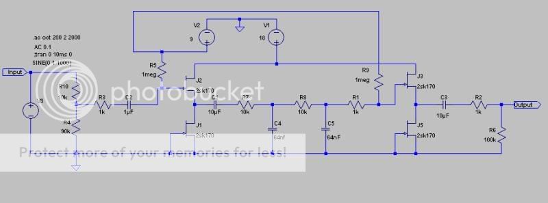
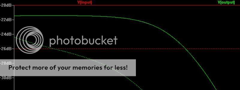
It is 6.8 db down at 150 Hz compared to the -20dB input, so it looks promising.
I just added another B1 and placed R7 + R8 and C4 + C5 between the two B1's.
Is that all? Or are there more into it?
It is 6.8 db down at 150 Hz compared to the -20dB input, so it looks promising.
stigaard123 said:I saw with some interest, that a solution for a active crossover was possible with this simple and hopefully good sounding buffer. For a start I would like to make a active low pass crossover with 12db at 150 Hz.
I just added another B1 and placed R7 + R8 and C4 + C5 between the two B1's.
Is that all? Or are there more into it?
It is 6.8 db down at 150 Hz compared to the -20dB input, so it looks promising.
I think your C4 should be connected to output instead of ground to get it right...
deja vu ?
http://www.diyaudio.com/forums/showthread.php?postid=1555159#post1555159
stigaard123 said:I saw with some interest..........
http://www.diyaudio.com/forums/showthread.php?postid=1555159#post1555159
- Home
- Amplifiers
- Pass Labs
- B1 Buffer Preamp