Zen Mod said:
certainly ;
besides that - I wrote "...... even less" .
in any case - if you have problems with offset - then make small delay circuit which can switch off relay after 5-10 seconds ; relay contacts connected as short from output side to gnd
Thanks Choky
I'll go for 30+ sec

BURNER said:
Thanks Choky
I'll go for 30+ sec
off course - in my previous post I meant on delay circ which will switch ON relay after some time ....... output of buffer is grounded via NC contacts .
plain delay circ with small darlington , few resistors and cap is good enough
Some help please
Hi,
A newbie here again.
I just want to copy the original B1 design without doing much work on the PSU, as I feel it is safer if I use something ready made.
So, I would be grateful if someone could tell me if in principle this 18V PSU would work:
http://www.effectpowersupplies.com/...25.137.100/module.aspx?ModuleNo=96962&doy=1m8[/url]
Many thanks
Antonio
All you need is a cheapie $5 or less wallwart. Honestly.
You probably have one in your basement in that box o' cables and other junk you dont need anymore but since it was attached to something that cost a lot like a computer or router we seem to keep them in a big ol' box.
Just find one that is around 18V and you will be fine. It needs only 20ma so I doubt you can find an 18VDC wallwart that wont work.
Uriah
edit: in regards to your website
http://www.effectpowersupplies.com/18v-dc-regulated-power-supply-7-p.asp
will work fine, but its overpowered and expensive.
Thanks Udailey,
I have not found 18V ones anywhere. What I found in shops are 9V and 12V ones.
Edit:
I think I will use two 9v ones and follow Zen Mod's kind suggestion: http://www.diyaudio.com/forums/showthread.php?postid=1569192#post1569192
I will keep looking.
Gosh, I hate the electrical part if DIY :
Regards
Antonio
I have MANY 48VDC supplies available if they could be adapted to work. Note they are 120-240VAC compatible.
If anyone is interested they're free + shipping.
Here is a link someone ELSE has on ebay. I just have several of the same ones that are free and taking up space.
http://cgi.ebay.com/CISCO-AIRONET-V...ryZ91357QQssPageNameZWDVWQQrdZ1QQcmdZViewItem
If anyone is interested they're free + shipping.
Here is a link someone ELSE has on ebay. I just have several of the same ones that are free and taking up space.
http://cgi.ebay.com/CISCO-AIRONET-V...ryZ91357QQssPageNameZWDVWQQrdZ1QQcmdZViewItem
A Sanchez said:Thanks Troy, but I read somewhere that the B1 requires between 18VDC and 24VDC.
I have run those buffers as high as 40V.
Guys, I have looked in an old parts box and I have 10x 2N5459 and 6x 2SK170BL. The 5459s bunch around 5-6mA Idss. And I measured 2 matches. 2x5mA & 2X5.2mA. The 170s are 6.9, 8.7, 7.7, 6.8, 8.2, 7.35 mA.
What do you think? Use the 5459 pairs for an attempt on a hopefully capacitorless B1, or prefer the 6.9+6.8, 7.7+7.35 mA 2SK170s? The 5459s have a dB or so more noise on paper, but for a line buffer isn't a big deal. ----The main question is, do 2SK170s sound detectably better than mundane N-JFETs, when noise is not an issue?---- Does anybody know? Nelson?
I can make it on perfboard, complete with 317-337 symmetric supply and lose at least the input cap. I will also use an output delay relay circuit if the equilibrium offset is very low so to lose Cout too, and avoid turn on thumps. The 5459s look like yummy matched pairs for that goal, and I can save the 2SKs for some single ended 2 stage zero feedback MM preamp where I can match their gain by Rs. I can not find more 2SKs right now at the shops.
Basically it will be nice to have a tiny buffer box that sounds decent and is mobile. Interesting to see how it performs against my preamp too (in attachment).
Attachments

Its a bit difficult to sound better than a single stage SE open loop 5W idling, common cathode triode with valve rectified and FET regulated B+. The JFets are solid state low voltage pentode imitators and a follower means 100% local feedback. Plus I have done JFet circuits before and they are better than op amps but play second fiddle to good tube circuits in general.
My intention is a general use wee box with excellent value. I like making little clever things. Having a good reference I can evaluate its merits more correctly. That is one of the reasons I want it sans caps.
Does anybody know if 2N5459 gives a sonic penalty VS 2SK170 at 3VP-P CD level and no gain? It is a very available, cheap JFET that bunches very well for Idss by 10 pieces sample.
salas said:.......
Does anybody know if 2N5459 gives a sonic penalty VS 2SK170 at 3VP-P CD level and no gain? It is a very available, cheap JFET that bunches very well for Idss by 10 pieces sample.
I think that you'll probably will not hear difference , once when you find sweet spot for 5459
I'm putting together my parts list for the B1. Re: the Diode D2... There is no number so I guess this would be any LED any color rated at 2 to 2.5 volts and plugged into the pc board? Mouser shows "Fairchild J109" as a cross refrence match for 2sk370. This number is in stock and a dozen cost $3.24. will the Fairchild J109 work for the B1 application?
Hello, another n00b here
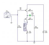
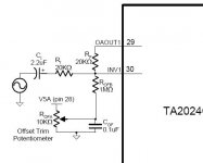
The B1 looks simple enough that I would consider building it as an input buffer for my TA2024 based amp.
Questions are now:
1) I run the amp from a single-rail 16.5V SMPS. Will this be enough to also drive the B1?
2) The TA2024 has 2.2 uF MKT input coupling caps, a 20k input resistor and a DC null circuit as depicted in the schematic on p.11 of the datasheet
http://pdf1.alldatasheet.com/datasheet-pdf/view/143080/TRIPATH/TA2024C.html
(see also attachment)
I guess it doesn't make an awful lot of sense to have this input in series with the 10uF output caps of the B1.
How can I best adapt the output of the B1 for this intended use?
Thanks for any advice
Attachments
Tolu said:
Have you tried it?
Your vote please!
I managed to discover another 9 pieces 2SK170BL. I have a couple of good matches now. What do you prefer me to make and test? The 2N5459 symmetric supply B1 spin off, or a 2SK170BL one?
- Home
- Amplifiers
- Pass Labs
- B1 Buffer Preamp