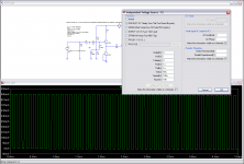
1nF with 1k gives 1us RC time constant for the Input low pass filter. That has F-3dB ~160kHz.
That amount of filtering is not liked by most listeners. They hear some loss of treble signal.
You can try experimenting with values of 680p, 470p and 330p to see if these are more to your liking.
That amount of filtering is not liked by most listeners. They hear some loss of treble signal.
You can try experimenting with values of 680p, 470p and 330p to see if these are more to your liking.
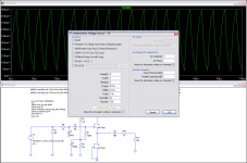
this question is typical from Members who do not follow the relevant Threads containing all the anecdotes of the "sound effect" of the various band limiting filters that are usually fitted to the inputs of Power Amplifiers................F-3dB ~160kHz, it's a quite high frequency, how can anybody could ear some loss of treble signal ?...........
Why do Members so often refuse to read the information that is here?
It's common to aim for an F-3dB point at least 10x higher or lower than the limit of the range you're trying to reproduce (20khz in this instance, so 200khz) to avoid noticeable attenuation or phase distortions within the target range of accuracy (20hz to 20khz).
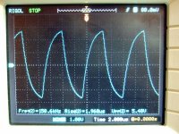
My function generator puts out its best SQW at 1/20 its nominal -3dB high band ability, rounds slightly at 1/10, and gradually loses performance to obviously rounded the higher I push it. It was the same for my older analog one not only the newer DDS which has to be filtered for ringing at a point, its the same ratio from its rougher but best rise time TTL output. Any 3MHz-5MHz decent generator will do fine for audio, will give 150-250 kHz most excellent SQW.
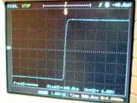
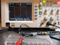
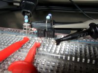
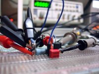
To put some hardware in this spice infested world, here is what a quick B1 symmetrically powered with 220R gate stopper can pass @150kHz with budget 3MHz gen to a budget hacked scope. Well, I aim for AIM TTI gear when better heeled after the next aeon, LOL.
Attachments
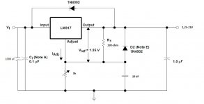
I do not like the 317 regulator sending noise back into the input of the FET buffer.
I think the 317 should take it's supply from the 18Vdc line.
The 317 also needs it's stability caps on the input and output.
The 317's performance improves significantly if a cap is added in parallel to VR1. Without these caps, it cannot match the performance of a 7805.
Hello Andrew and alls.
I´m thinking put this PSU for my B1 (I´m waitting for the parts at this moment).
Do you think I´ll have problem with the noise? Will the rippe enoght low?
Thank you very much
Jose
Attachments
I used a similar regulator with a 30VA transformer and it was silent.
The B1 isn't super sensitive to PSU choice. I used 4700uF + 2R2 + 4700uF CRC into the LM317.
Thanks you very much for your reply KatieanDad.
Sorry a lot but I´m no sure understand exactly your schematic.
where did you put 4700uF + 2R2 + 4700uF CRC? In the place of 1.0 uF capacitor? Replacement 1000 uF and putting 2r2+4700 uF at the end?
Regards
Last edited:
It will be in place of the 1000uF cap. For a demonstration of what this does see my blog post http://www.diyaudio.com/forums/blogs/wintermute/574-yarps-finally-some-progress.html look at pics 1, 2 and 3 which show the ripple accross the first cap, 2nd cap and third cap. The caps in this test were overkill and I ended up going with 4700-3r3-4700-3r3-1000 (which is probably also overkill) but it substantially reduces the ripple before the regulator, and since the regulator only reduces the ripple (doesn't eliminate it) making it smaller before makes it smaller after
The other thing I found was that having 5V difference input to output voltage resulted in the lowest noise on the output. Increasing over 5V in - out differential didn't make any further improvement.
Note that using a resistor in between the caps does drop the voltage, and that drop is proportional to current draw, so the more current your circuit pulls the bigger the drop, a standard B1 won't draw much current though
Tony.
http://www.diyaudio.com/forums/blogs/wintermute/574-yarps-finally-some-progress.html look at pics 1, 2 and 3 which show the ripple accross the first cap, 2nd cap and third cap. The caps in this test were overkill and I ended up going with 4700-3r3-4700-3r3-1000 (which is probably also overkill) but it substantially reduces the ripple before the regulator, and since the regulator only reduces the ripple (doesn't eliminate it) making it smaller before makes it smaller after The other thing I found was that having 5V difference input to output voltage resulted in the lowest noise on the output. Increasing over 5V in - out differential didn't make any further improvement.
Note that using a resistor in between the caps does drop the voltage, and that drop is proportional to current draw, so the more current your circuit pulls the bigger the drop, a standard B1 won't draw much current though
Tony.
the other big advantage of rCRC is that the second filter is more effective at attenuating the HF stuff that gets past the transformer and then gets past the rC.
The 3pin IC regulators have poor performance at HF and the system usually benefits from all the help you give the PSU to sound quiet (= clean DC).
The 3pin IC regulators have poor performance at HF and the system usually benefits from all the help you give the PSU to sound quiet (= clean DC).
Thank you guys.
Then, I´ll try put crc after. At the beginer I´ll try it with 1000 uF I have a handful of this. I think C1 lower the ripple too.
I´ll read your link Tony, I played changed cups with Duncan´s PSU desingers some years ago, but I´v not patient to learn use pspice or other sophisticated
software.
Then, I´ll try put crc after. At the beginer I´ll try it with 1000 uF I have a handful of this. I think C1 lower the ripple too.
I´ll read your link Tony, I played changed cups with Duncan´s PSU desingers some years ago, but I´v not patient to learn use pspice or other sophisticated
software.
- Home
- Amplifiers
- Pass Labs
- B1 Buffer Preamp