Back when NP first shared the JFET BOZ with us, I built the JBOZ but didn't get good results with my DAC (Zhaolu 2.5) because the output voltage was very high on the DAC.
(I know I'm gonna get kicked real hard for this one)

If I put the B1 between the JBOZ and the DAC, will this 'fix' the higher than normal DAC output voltage?
Thanks for any help

(I know I'm gonna get kicked real hard for this one)
If I put the B1 between the JBOZ and the DAC, will this 'fix' the higher than normal DAC output voltage?
Thanks for any help
twitchie said:Back when NP first shared the JFET BOZ with us, I built the JBOZ but didn't get good results with my DAC (Zhaolu 2.5) because the output voltage was very high on the DAC.
(I know I'm gonna get kicked real hard for this one)
If I put the B1 between the JBOZ and the DAC, will this 'fix' the higher than normal DAC output voltage?
Thanks for any help
repeat after me :
-we have pot in B1.........we have pot in B1.........we have pot in B1.........we have pot in B1.........we have pot in B1.........we have pot in B1.........we have pot in B1.........we have pot in B1.........we have pot in B1.........we have pot in B1.........we have pot in B1.........we have pot in B1.........we have pot in B1.........we have pot in B1.........we have pot in B1.........we have pot in B1.........we have pot in B1.........we have pot in B1.........we have pot in B1.........we have pot in B1.........we have pot in B1.........we have pot in B1.........we have pot in B1.........we have pot in B1.........we have pot in B1.........we have pot in B1.........we have pot in B1.........we have pot in B1.........we have pot in B1.........we have pot in B1.........we have pot in B1.........we have pot in B1.........we have pot in B1.........we have pot in B1.........we have pot in B1.........we have pot in B1.........we have pot in B1.........we have pot in B1.........we have pot in B1.........we have pot in B1.........we have pot in B1.........we have pot in B1.........we have pot in B1.........we have pot in B1.........we have pot in B1.........

Re: PSU...
Overkill.
Voltage rating is too high.
Vix said:Batteries, series regulator, shunt regulator....or, none of these...
Digging through my junkbox I have found two "small" capacitors, and I hope they'll be sufficient to provide enough filtering for B 1/2...
Overkill.
Voltage rating is too high.
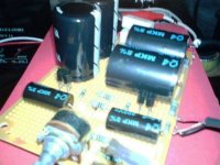
I finished B1 prototype on perf board.
It sounds wonderful with nice transparency and clarity.
Thanks very much Nelson for your great contribution on DIY community
My B1 is running on original part value published in Papa's article except 20K pot instead of 25K at the input.
-FET is 2SK170GR (no matching)
-MKP type 1uF & 10uF coupling capacitors
-power supply is +18.9V, BZLS aka
However, I got 30 mV offset at the B1's output when starting from cold.
Offset declines from 30 mV to 1-2 mV after 2-3 minutes warm-up then stabilized.
With the F5, it causes DC offset at speaker terminal around 400 mV then declines to 7-10 mV after few minutes as B1's offset goes down.
Anyone has the same problem?
I'm appreciated for any suggestion to resolve this problem.
Thanks
BURNER said:I finished B1 prototype on perf board.
It sounds wonderful with nice transparency and clarity.
Thanks very much Nelson for your great contribution on DIY community
My B1 is running on original part value published in Papa's article except 20K pot instead of 25K at the input.
-FET is 2SK170GR (no matching)
-MKP type 1uF & 10uF coupling capacitors
-power supply is +18.9V, BZLS aka
However, I got 30 mV offset at the B1's output when starting from cold.
Offset declines from 30 mV to 1-2 mV after 2-3 minutes warm-up then stabilized.
With the F5, it causes DC offset at speaker terminal around 400 mV then declines to 7-10 mV after few minutes as B1's offset goes down.
Anyone has the same problem?
I'm appreciated for any suggestion to resolve this problem.
Thanks
I have seen something like that too in my F5. Being directly coupled the F5 is pretty sensitive to little dc voltages at its input .
The cure for that is to connect the B1 to the F5 when the power of both is off . Then Power on the B1, wait a minute , and power on the F5 .
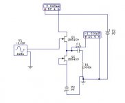
Zen Mod said:in 10 min. I'll post re-drawed circ for you
edit :
little more than 10 min
here it is : you can mount it in same case with chip/drek amp , using any type of IC or discrete voltage reg , to have nice and stable +/-9V , from same PSU ( of chipamp ) ;
dunno - probably LM317/LM337 will do the job for you , or nice discrete zenner followers
Hello Zen Mod
I prefer the symmetric supply because it loses the input capacitor.
I guess that if the NJFETs are chosen very close in IDSS we may lose even the output capacitor, yes?
At least I don't see any DC if simulating with theoretical devices (totally the same). Can't we put a null trimmer in real life?
Attachments
salas said:
Hello Zen Mod
I prefer the symmetric supply because it loses the input capacitor.
I guess that if the NJFETs are chosen very close in IDSS we may lose even the output capacitor, yes?
At least I don't see any DC if simulating with theoretical devices (totally the same). Can't we put a null trimmer in real life?
I can't see why we can't .........
feel free to put trimmer , but I'll not loose my sleep with proper 10uF in output ......... as Papa probably would say .
without servo - these critters are wandering around all the time ........
it's your choice what you'll use
BURNER said:Yes Choky, offset with 10uF
However, offset drops to 1-2 mV after few minutes.
supposed to be problem during charging period of MKP 10uF but I think it takes too long in my case
I'll try with another cap type though...
stefanobilliani said:
I have seen something like that too in my F5. Being directly coupled the F5 is pretty sensitive to little dc voltages at its input .
The cure for that is to connect the B1 to the F5 when the power of both is off . Then Power on the B1, wait a minute , and power on the F5 .
smaller resistor from output side of cap to ground - will speed up charging ; decrease it from present 221K value to , say , 100K 0r even less
Zen Mod said:
smaller resistor from output side of cap to ground - will speed up charging ; decrease it from present 221K value to , say , 100K 0r even less
That is R105 and R205 of the B1's circuit .
no, the output resistor dissipates stored charge when the amp is dormant.stefanobilliani said:
That is R105 and R205 of the B1's circuit .
A similar resistor for the input cap will bring both input and output of the respective units to DC zero volts and allows connection between units without a transfer of charge between the caps.
At switch on the 100k, or 1M0 if you prefer, has almost no effect on the way the caps charge up and the way they pass signals once partially/fully charged.
Zen Mod said:
without servo - these critters are wandering around all the time ........
Hi Zen, could you elaborate on what you mean by this?
I'd be very interested in getting rid of both input and output caps if possible, as they are probably the biggest influence on the transparency of this circuit.
Do you mean dc offset would still be a problem with a dual rail supply?
Also wondering why Nelson built this as a single rail supply, as the dual rail alternative seems to need fewer parts?
No disrespect to the maestro intended.
float said:
Also wondering why Nelson built this as a single rail supply, as the dual rail alternative seems to need fewer parts?
No disrespect to the maestro intended.
Just speculation here, but it seems to me that a dual rail supply only uses fewer parts if you happen to have +/- 9V DC (or so) already. A single rail allows you the convenience of using any old wall wart. Further, I'd imagine that the big man would encourage you to modify to your heart's content.
-d
Have not built this buffer yet (hopefully soon) but I am intending to use a bipolar PS and no caps. I do have 2SK389 but from what I understand so far you just might get away with 2SK170s, preferably matched for Idss as closely as you can and off course thermally coupled (e.g. glued together). If you have an offset after warmup you might try and tweak the + or - voltage ever so slightly.
float said:
Hi Zen, could you elaborate on what you mean by this?
I'd be very interested in getting rid of both input and output caps if possible, as they are probably the biggest influence on the transparency of this circuit.
Do you mean dc offset would still be a problem with a dual rail supply?
Also wondering why Nelson built this as a single rail supply, as the dual rail alternative seems to need fewer parts?
No disrespect to the maestro intended.
simple jfet circuits have tendency of changing current in time domain ,strictly dependable of jfet temperature change ;
if you can secure steady temperature conditions for them ( closed case , or case with controlled amount of air circulation) you'll have so-so stable offset on output , but not in time domain .
point is that we don't have DC feedback path , which can secure offset stability
Diomedian said:
Just speculation here, but it seems to me that a dual rail supply only uses fewer parts if you happen to have +/- 9V DC (or so) already. A single rail allows you the convenience of using any old wall wart. Further, I'd imagine that the big man would encourage you to modify to your heart's content.
-d
agree with all that ;
as said numerous time ( at least from humble me ) Papa's main intention and probably satisfaction is to see that some of his spoiled (veeeeeeeeerrrry spoiled ) kids use gray cells sometimes .
in same time , you can learn (and see - in first place ) few things from his gadgets - humor and simplicity . nothing bigger than life itself .... as in some other constructions circulating around

hehe - I can't find smiley rotten enough for that last sentence
- Home
- Amplifiers
- Pass Labs
- B1 Buffer Preamp