Hi folks.
Nearing completion of my stock B1 Buffer.
In the interests of keeping the wiring neat in my particular setup, and cutting out a few inches of PCB traces into the bargain, is it OK to route the input wiring directly to the DPDT switch, then onto the volume pot, and only then into the B1 PCB? I have already added a jumper onto the PCB to route the Left/Right Input-1 directly to R102/202.
The only change to the circuit that I can see from doing it this way is the 1M to ground on the inputs would be after the volume control, not before.
Just wanted to check this slight mod is OK before wiring it up")
Ta,
- John
Nearing completion of my stock B1 Buffer.
In the interests of keeping the wiring neat in my particular setup, and cutting out a few inches of PCB traces into the bargain, is it OK to route the input wiring directly to the DPDT switch, then onto the volume pot, and only then into the B1 PCB? I have already added a jumper onto the PCB to route the Left/Right Input-1 directly to R102/202.
The only change to the circuit that I can see from doing it this way is the 1M to ground on the inputs would be after the volume control, not before.
Just wanted to check this slight mod is OK before wiring it up
Ta,
- John
You could do it that way, and if you were lucky it might even work. But the PCB is set up to take the volume pot in a certain way -- I wouldn't change that.
If you were going to use a switch with room for more than 2 inputs then wiring it up to use that is a good idea.
But if not, why mess with a good thing? That board is very quiet when wired properly.
If you were going to use a switch with room for more than 2 inputs then wiring it up to use that is a good idea.
But if not, why mess with a good thing? That board is very quiet when wired properly.
Fair enough, but if you trace the PCB refering to the schematic I cannot see why it wouldn't work like this, and as I said I am doing it this way to tidy up the wiring in my particular build (the PCB has to be lengthways unfortunately). It was just the input 1M resistor being changed to after the pot which I was slightly unsure about, whether that would cause any problems...
- John
- John
Seems like I have a PSU problem instead which I need to sort out first now
Thought I'd better test the PSU before wiring up all the signal lines. It's a Peter Daniel universal PCB board, which has worked fine for several other projects in the past. I'm using an LM317T set to 24V output. 1000uF 50V cap before & after the regulator. 1uF tantalum caps right next to the input/output legs of the reg as per the datasheets. Just tested the PSU on its own and get a solid 24V output.
However when I connect the PSU to the B1 Buffer the measured voltage is only 0.234V. Cannot figure it out - all the wiring is fine, no shorts. Is this a sign of the PSU 'wilting' under load for some strange reason? I measured the output both on the B1 PCB and the output of the PSU and both are the same/low.
I'm sure it must be something simple as I've had the B1 board up and running in the past.
Any suggestions please?
Cheers,
- John
Just about to answer my own question haha!
Thought occured to me to run a continuity test between + and - on the PSU input and I get a reading. So I have a short it seems. I'm using one of those PCB screw terminal blocks on the B1 PSU input so perhaps that's gone south...
Should there be a continuity reading between the + and - on the PSU input on B1?
Last edited:
If you load the transformer with a 20 kOhm resistor, then it plus your existing attenuator in parallel will yield 10kOhms.
+4dBu is sine wave peak amplitude of 1.737 V, or peak to peak twice this. Just make sure you have sufficient DCPS headroom to accomodate lots more than that. The JFETs are rated at max V_DS = -30 to -40 volts, but they are matched generally at -10 volts.
I am going to add 1 M-Ohm resistors in parallel to the grounding "isolation" diodes, set the DC ground levels to zero but allow AC float, but it is already extremely quiet, so I dont know if this will be an improvement or not.
John,
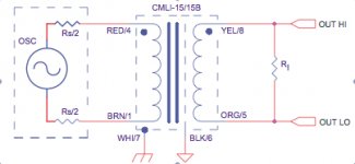
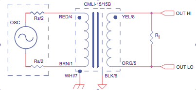
I just got my transformers and I have a question. Since I am running, initially at least, unbal to unbal, my input would be Red/Brwn; output Yel/Or. I would tie White/Blk together to common (and chassis in this case) ground. Is this correct on the White/Blk? I am using Cinemags. See photo attached.
Thank you.
Attachments
Just about to answer my own question haha!
Thought occured to me to run a continuity test between + and - on the PSU input and I get a reading. So I have a short it seems. I'm using one of those PCB screw terminal blocks on the B1 PSU input so perhaps that's gone south...
Should there be a continuity reading between the + and - on the PSU input on B1?
Anybody? I know it's probably a simple question & laughably so, but I'm no expert alas. I Have desoldered the terminal block and that's tested OK. So perhaps the first B1 PSU capacitor (C1) has developed a short? Putting a meter onto the + and - pads on the PSU input tests positive for continuity...
Last edited:
Just removed C1 (a royal PITA with this through hole plated PCB) and I am still getting continuity reading on my multi-meter when putting the probes onto the + and - pads on B1 power input. Any ideas folks? SHOULD I be getting continuity? Could this be a problem with R2/R3 perhaps?
Ta,
- John
Ta,
- John
grounding, when using transformer isolation
I presume you are using the input transformer for isolation, to break ground loops and avoid tunneling noise into the audio circuit. In this spirit,
I would make black to be signal ground for unbal output. White to be ground for unbal input, and DCPS. I suggest that chassis ground should be tied via (dual diodes, transorbs, or varistors) plus resistors (eg 1 MegOhm) separately to both grounds.
Tom Intrator
John,
I just got my transformers and I have a question. Since I am running, initially at least, unbal to unbal, my input would be Red/Brwn; output Yel/Or. I would tie White/Blk together to common (and chassis in this case) ground. Is this correct on the White/Blk? I am using Cinemags. See photo attached.
Thank you.
I presume you are using the input transformer for isolation, to break ground loops and avoid tunneling noise into the audio circuit. In this spirit,
I would make black to be signal ground for unbal output. White to be ground for unbal input, and DCPS. I suggest that chassis ground should be tied via (dual diodes, transorbs, or varistors) plus resistors (eg 1 MegOhm) separately to both grounds.
Tom Intrator
Tom, you are very patient, much appreciated, thanks.
Yes, this is primarily for isolation and to hear if I like the transformer sound.
Following your advice, I would tie the WHITE lead to DC PS ground through a 1 megOhm resistor. I assume that resistor will act as a drain and will limit current in the event of a major malfunction.
For the BLACK signal ground on the transformer output, I will tie that through a 1 megOhm resistor to pot terminal #1 or it's corresponding pad on the circuit board.
This is very instructive and doing it has made your elegant B-1 differential setup come into sharper focus.
use the diodes as well, or 10 ohm resistor. MegOhm is only useful in parallel with something of much lower impedance like the diodes.
Folks, when testing a stock PCB built B1 Buffer, is there meant to be a continuity reading on a multimeter when putting the probes onto the + and - pads at the DC input on the PCB?
If not I cannot see why I am getting a short, unless perhaps D1 or R2 are faulty? Both appear to test fine in circuit though...
- John
If not I cannot see why I am getting a short, unless perhaps D1 or R2 are faulty? Both appear to test fine in circuit though...
- John
How do you mean continuity ?
There are R2(10K) and R3(10K) across V+ and 0V, also there is R4(15K) and LED D2, and of course C1.
Between that lot you will never get an insulation type reading.
My guess is that C1 is just not charging with your meter probes attached.
Try removing it and test again.
There are R2(10K) and R3(10K) across V+ and 0V, also there is R4(15K) and LED D2, and of course C1.
Between that lot you will never get an insulation type reading.
My guess is that C1 is just not charging with your meter probes attached.
Try removing it and test again.
Last edited:
Try connecting 24V (or whatever you are using) supply to it with say 1K in series.
Then measure the DC voltages around the amp.
The total draw of the B1 including its LED (D2) is only about 2mA so you will lose about 2V across the series resistor if everything is OK.
It has been muted that the B1 is good up to about 36V, I've only ever gone as far as 30V.
Then measure the DC voltages around the amp.
The total draw of the B1 including its LED (D2) is only about 2mA so you will lose about 2V across the series resistor if everything is OK.
It has been muted that the B1 is good up to about 36V, I've only ever gone as far as 30V.
Last edited:
By continuity I mean I got a beep on the multimeter to show there's a circuit (or a short). If I touch the two probes together I get the same beep. I ran this check as initially when I first turned on the PSU I got approx. 0.235v reading at the DC input to B1. Not even the LED lit up.
Disconnecting the PSU and measuring it I got the expected 24V DC.
I then discovered this 'continuity' or short between the + and - DC input on B1. Figured it might be C1 (that measured as a short in circuit) so took that out, and typically that measured fine afterall!
Is one meant to get a 'continuity' reading between the + and - DC inputs on B1? If so perhaps everything is actually OK and it takes a minute or so to 'charge up' or something? Just figured getting the continuity or short 'beep' on the multimeter when over C1 or the DC input wasn't a good sign?
- John
- Home
- Amplifiers
- Pass Labs
- B1 Buffer Preamp