Nelson Pass said:How long do you suppose the batteries will last?
Battery will last until empty ... or close to.
nelson my old partner
did you see this following nice post of mine in this topic
it is written like from a friend to a !fiend!
I wish for to have a response (= positive! feedback) from you, yourself
from whom I adressed
")
thanks, Lineup Audio Lab - a bit drunk on sherry wine - this evening ....
lineup said:Great you have published your B1 papers, Nelson.
thanks.
Keeep on going oldtimer. (although I am tiny bit older born in May 1951)
Very nice to see age is not something that can kill off creativity.
Good hope for all young audio diy guys.
This hobby is something they can do for very long time.
Maybe until their final breath .. on that Very Last Day
Lineup - now waiting for the investigations and findings that Mr Pass will do in B2
Nelson Pass said:How long do you suppose the batteries will last?
Typical 9V battery is about 500 mAh, with a 20mA drain, and 2 batteries, you'd expect 40-50 hours? Unless I'm oversimplifying?
-d
Nelson Pass said:How long do you suppose the batteries will last?
There's an option to have two rechargeable 9 v Ni-Mh ones. Then build a trickle charger that would charge when the B2 is off...
On the other hand, a cheaper and less complicated solution would be to use 7812 and 7912 regs. (I'll most probably go for this one...)
Thanks,
Vix
Vix said:
There's an option to have two rechargeable 9 v Ni-Mh ones. Then build a trickle charger that would charge when the B2 is off...
On the other hand, a cheaper and less complicated solution would be to use 7812 and 7912 regs. (I'll most probably go for this one...)
Thanks,
Vix
ya lazy greenhorn

proper shunt reg is better than batteries
Zen Mod said:
ya lazy greenhorn
proper shunt reg is better than batteries
I agree...
Me lazy
udailey said:Well, if you divide 20 into 500 you will end up with 25. However, while they should run a little less than that you have to take into account the proper burn in time of a 9V battery to get the best sonics
...but 2 batteries for a total of 1000 mAh.
Course you could always run your batteries in on something a little less demanding - in this application I prefer a pair of 12.6V car batteries, and initially I wait until it's -30C (-22F) and just start an SUV over and over for a couple of hours. I find the Motomaster "Eliminator" series of batteries from Canadian Tire provide the best sonics. Also, you should use pure copper jumper cables, and be sure to design your chassis to make safe usage of car battery terminals.
-d
I am using this transistor.................
Phillips BF861B
This one is available from DIgikey. It seems to match the specs quoted in Nelson's article, it's cheap, and from the datasheets- it looks to have good performance.
I have attached my design of a pcb that I came up with in order to utilize the smd jfets.
I'll attach the other one without the ground plane on the next post.
Attachments
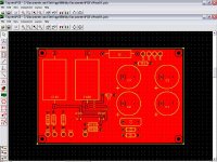
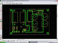
Here's another one..............
This one is sans ground plane.
You would need two of these for stereo.
As you can see, the PSU is on board; the electrolytics I'm using are 2700uF Panasonic FM.
There are pads on the board for power in out, led, input, and the pot.
Also note that here is room enough for those big-honkin' coupling caps that we all like to use.
I wanted to purchase Mr. Pass's boards, but I didn't know if they would be configured for SMD devices.
Thank you for sharing your designs with us Mr. Pass, I've been waiting for a simple design like this for a while.
Attachments
BTW..........................
I've been reading some of the posts about using a battery supply for this buffer, but in my opinion- the current draw in this circuit is so low- and the capacitance is so high that all you'd really have to do is perhaps use EMI filtering on the AC side- and refrain from using switching power supplies.
As far as the rectification in cheap "wall-warts" go, you could always opt for an AC "wall wart"- and use hexfreds on the board itself.
square wave measurements
I just have read the article of NP in enjoythemusic.com. What surprised me a little bit was the figure of the 200kHz measurement of square waves.
The B1 was praised with high bandwith and low distortion. So, the square waves at fig. 5 were at first half more than sine waves. Yesterday I had a long conversation at a birthday party with M. Bayer of Omtec Audio (e.g. phono pre Antares) and he told me that his class A devices all have perfect measurement results up to 500 kHz. He always develops only with his measure equipment and not with his ears.
Not sure what you are trying to say ? Are you shure you are not mixing up bandwidth response with the reproduction of sqare waves of a given frequency? From the article: "... Figure 5 below shows a 100 kHz square wave at 1 volt at the output. The bandwidth of the preamp is -3dB at about 700 kHz." Btw. it says 100 KHz in the text and 200 KHz in the accompanying chart.
P.S. ONLY developing with measurement equipment and not with his ears says a lot about Mr. Bayer.
P.S. ONLY developing with measurement equipment and not with his ears says a lot about Mr. Bayer.
I have nov finised a B1 version with 10uF BGF for coupling capacitors, 2sk163, 680K gate resistors and 820ohms for series in and output resistors (parts from the home stock).
Supply is 24V from capacitor multiplier and it sounds wonderfull and no hum/noise audible at all
One question:
I am planning a ICEpower poweramp with a 8k input resistance and 1.2V sensitivity. Will this match the B1?
Or is it possible to reduce the output series resistor to ex. 100-200 ohms?
Supply is 24V from capacitor multiplier and it sounds wonderfull and no hum/noise audible at all
One question:
I am planning a ICEpower poweramp with a 8k input resistance and 1.2V sensitivity. Will this match the B1?
Or is it possible to reduce the output series resistor to ex. 100-200 ohms?
Tolu said:@NP
When will the PCBs for B1 be available?
"Soon".
Just relax, and use a perf board or a vector board if need be.-d
- Home
- Amplifiers
- Pass Labs
- B1 Buffer Preamp