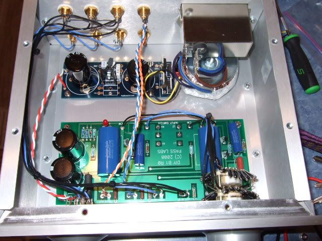
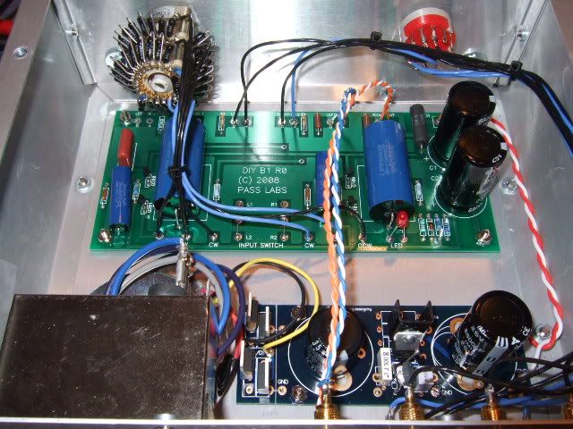
My B1 is up and running!
congrats, looks good
just yesterday I decided to build myself a B1 with "Lightspeed" attenuator, yeah
Here is my build thread - lots of pictures and much more information;
http://www.diyaudio.com/forums/pass-labs/181552-b1-preamp-build-thread.html
http://www.diyaudio.com/forums/pass-labs/181552-b1-preamp-build-thread.html
Here is my build thread - lots of pictures and much more information;
http://www.diyaudio.com/forums/pass-labs/181552-b1-preamp-build-thread.html
I see the output RCA side grounded to the PCB but I don't see an input RCA ground reference. Did you miss something or did I?
In similar situations I generally tend to tie all the isolated back panel RCA grnds together and have one (or two if I kept them separate) ties to the PCB.
EDIT: Oh but beautiful job. Neat and well organized. Pretty chassis too!
6L6-
Gotcha. Never saw the blk grd wires.
I saw this picture and didn't see the addition of the two more blacks later in the build.
http://i198.photobucket.com/albums/aa276/aeroplane_album/DSCF3537.jpg
Gotcha. Never saw the blk grd wires.
I saw this picture and didn't see the addition of the two more blacks later in the build.
http://i198.photobucket.com/albums/aa276/aeroplane_album/DSCF3537.jpg
Last edited:
Here is my point-to-point version:
An externally hosted image should be here but it was not working when we last tested it.
An externally hosted image should be here but it was not working when we last tested it.
B1 p2p
hi,
I thought i would share a photo of the guts of my p2p b1.
pretty excited about this, i just tested it quickly and seems to be working perfectly.
Now i just need to make a little case for final hookups!
hi,
I thought i would share a photo of the guts of my p2p b1.
pretty excited about this, i just tested it quickly and seems to be working perfectly.
Now i just need to make a little case for final hookups!
An externally hosted image should be here but it was not working when we last tested it.
I only plan on switching between two sources...
I planned on using a toggle. I have some SPDT. I noticed most people are using DPDT switched.
Is there any advantage to switch the ground also?
thanks
DPDT is not for left/right instead of ground for second pole ?
DPDT is not for left/right instead of ground for second pole ?
Thanks right, stupid question i dont know what i was thinking. I puts some dpdt on order the other day when i was thinking straight. I was debating on using two before i bought those on using two single poles to get the build done... but forgot temporarily that i need two, i can wait a few days
trying to understand the PS
Hi,
I've been thinking about the B1 (actually build one as well) and it's power supply.
As I see it, the concept is: take a descent DC-supply. Then follow that by a RC-filter (R1, C1, C2, C3 in the original schematic) to have a really nice supply.
Of course the PS impedance gets larger (R1 is doing that) but that is apparently not a problem because (now follows my thinking )
)
1. the B1 draws only a little and fairly constant current?
2. there is enough capacity after R1 to provide the current needed (see 1.)?
If this reasoning holds, then increasing R1 gives us a lower corner frequency (less HF-noise), without penalties (the increased PS impedance is not a problem, see 1 and 2).
Please enlighten me, does this reasoning hold, or am I missing something important?
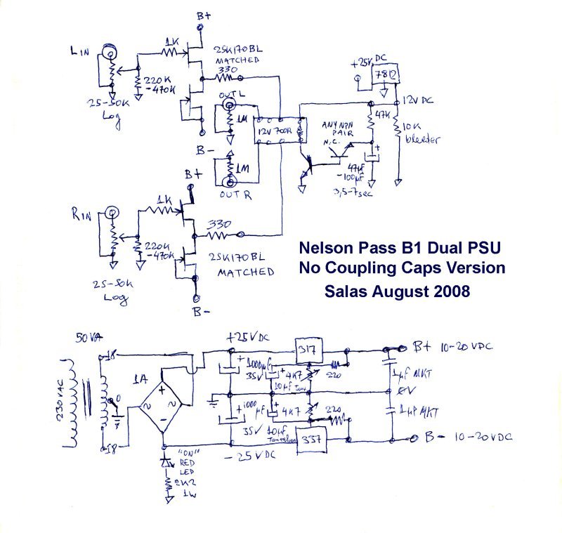
The reason I ask (of course I'd like to understand) is that if this holds, it's very easy to make a symmetrical B1 which is much more in line with the original asymetric circuit by Pass than the interesting circuits proposed by Salas (as mentioned in e.g.: http://www.diyaudio.com/forums/pass-labs/145201-building-symmetrical-psu-b1-buffer.html).
It goes like this:
Start with the (first?) symmetrical schematic by Salas http://www.diyaudio.com/forums/attachments/pass-labs/134693d1243979226-building-symmetrical-psu-b1-buffer-b1psu2xsmall.jpg. Leave out the LM317/LM337 stuff.
Take a decent symmetrical DC-supply. Follow that by an RC-filter, where the R is a preset, and feed the circuit by Salas with it. The DC-offset can then by nulled by virtue of the presets.
See pic:

Please comment on this setup. Is its smart? Is it stupid? Are regulators (LM3x7) better?
Thank you, MArco
Hi,
I've been thinking about the B1 (actually build one as well) and it's power supply.
As I see it, the concept is: take a descent DC-supply. Then follow that by a RC-filter (R1, C1, C2, C3 in the original schematic) to have a really nice supply.
Of course the PS impedance gets larger (R1 is doing that) but that is apparently not a problem because (now follows my thinking
) 1. the B1 draws only a little and fairly constant current?
2. there is enough capacity after R1 to provide the current needed (see 1.)?
If this reasoning holds, then increasing R1 gives us a lower corner frequency (less HF-noise), without penalties (the increased PS impedance is not a problem, see 1 and 2).
Please enlighten me, does this reasoning hold, or am I missing something important?
The reason I ask (of course I'd like to understand) is that if this holds, it's very easy to make a symmetrical B1 which is much more in line with the original asymetric circuit by Pass than the interesting circuits proposed by Salas (as mentioned in e.g.: http://www.diyaudio.com/forums/pass-labs/145201-building-symmetrical-psu-b1-buffer.html).
It goes like this:
Start with the (first?) symmetrical schematic by Salas http://www.diyaudio.com/forums/attachments/pass-labs/134693d1243979226-building-symmetrical-psu-b1-buffer-b1psu2xsmall.jpg. Leave out the LM317/LM337 stuff.
Take a decent symmetrical DC-supply. Follow that by an RC-filter, where the R is a preset, and feed the circuit by Salas with it. The DC-offset can then by nulled by virtue of the presets.
See pic:
Please comment on this setup. Is its smart? Is it stupid? Are regulators (LM3x7) better?
Thank you, MArco
- Home
- Amplifiers
- Pass Labs
- B1 Buffer Preamp