Hi
I built a PLH several months ago, am enjoying a lot the sound.
Lately with the heated discussion of using JFET, I am thinking about what benefit it might bring if I subsitute the 1st stage of the PLH, which is an IRF610 by a JFET. I have a few "used" 2SK147 on hand which I want to re-use.
The IRF610 in PLH is biased to over 10mA, seems a bit high for a JFET. If I trim down the bias to a couple of mA, will that be sufficient to drive the MOSFET output stage - reading so much about the capacitance of the MOSFET.
Any advices?
Thanks Nelson,
if you can, would like to hear some hints from you on the probable sonic difference by making this change.
Then, here is my thought design process, and would like to receive comments or suggestions:
I get only 5 2SK147BL on hand, so at most I can get 2 in parallel per channel.
System performance:-
The IRF610 is biased at close to 12mA in current design. Transconductance is hard to read from the data sheet, which use Ampere as X-axis. But still I believe at 12mA, the transconductance must be below 100mS.
The transconductance of 2SK147 is 40mS, so 2 in parallel gives an effective value of 80mS.
For BL grade, IDSS is 8mA to 16mA, so I believe running them at ~6mA should be OK.
Hence I think a straight drop-in should not affect the open loop gain that much, if I keep the load resistance and source resistance unchanged.
Bias considerations:-
The source of the 2SK147 will still be around 4.6V, which is controlled by the lower output MOSFET. The gate of 2SK147 however, will be at about 0.2V lower, so around 4.4V above ground. I need to change the resistor above the 50K trimpot to allow me to trim back to 20V DC output. This seems to be only change I need to make.
Reliability:-
This is the one that concerns me most. The Drain voltage, in the worst case when P2 is completely shorted, will be at about 29V above ground. While the source is at 4.6V, the voltage across the JFET will be 25V. The breakdown voltage is 40V, so I only have 15V margin.
With 6mA drain current, 25V across, the power dissipation is about 150mW, which is 25% of the max dissipation of 600mW. I hope I can get away without a heat sink.
Nevertheless on paper, seems that 2 2SK147 in parallel should survive.
Hence as a summary, it appears that I only need to change 1 resistor and do some retrimming only. Seems like an easy one?
Hi, just want to report that my PLH-J is born.
This morning, I followed the design thought process to modify my PLH to incorporate JFET as input stage.
Out of the 5 2SK147BL, I measured their IDSS and found 2 very close at 12.2mA, and 2 very close at 11.8mA, the remaining one at 9.7mA. So naturally 1 got 2 pairs.
Pulling out the IRF610, replacing them by a pair of 2SK147. Then I bypassed the R7 47K resister with a 10K resistor to enable me to adjust the 20V DC out.
Everything worked fine with this simple modification.
The voltage across the 2SK147 was measured at about 20V. So at 6mA, the dissipation is 120mW. I noted that in F5, the 2SK170 is also biased at 6mA with a Drain-Source voltage also at 20V. And there is 200mW margin more in 2SK147 compared to 2SK170. So I feel good about the working conditions.
How about the sound? Well, only have about an hour of audition till now. The PLH and PLH-J sounds rather similar. But it is quite obvious that the "focus" is sharper in PLH-J, meaning that the instructments or vocals stand out from the background clearer. Sound stage seems to be improved also. But more audition is needed to confirm.
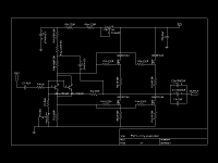
Unfortunately I do not have a software to create a schematics.
If you download the PLH pdf file from PassDIY, go to Fig 11, that's essentially the circuit. Modifications include:
a. R7 (the pdf is wrong, the value should be 47k based on article in AudioExpress) is replaced or shunted with a 10K resistor
b. Q1 is replaced by a pair of 2SK147BL JFET, Drain/Source/Gate positions are all the same as original Q1.
That's it.
FYC said:Hi, just want to report that my PLH-J is born.
This morning, I followed the design thought process to modify my PLH to incorporate JFET as input stage.
Out of the 5 2SK147BL, I measured their IDSS and found 2 very close at 12.2mA, and 2 very close at 11.8mA, the remaining one at 9.7mA. So naturally 1 got 2 pairs.
Pulling out the IRF610, replacing them by a pair of 2SK147. Then I bypassed the R7 47K resister with a 10K resistor to enable me to adjust the 20V DC out.
Everything worked fine with this simple modification.
The voltage across the 2SK147 was measured at about 20V. So at 6mA, the dissipation is 120mW. I noted that in F5, the 2SK170 is also biased at 6mA with a Drain-Source voltage also at 20V. And there is 200mW margin more in 2SK147 compared to 2SK170. So I feel good about the working conditions.
How about the sound? Well, only have about an hour of audition till now. The PLH and PLH-J sounds rather similar. But it is quite obvious that the "focus" is sharper in PLH-J, meaning that the instructments or vocals stand out from the background clearer. Sound stage seems to be improved also. But more audition is needed to confirm.
Hi,
Any further comments on your very interesting project?
Sound? Still working?
")
Yes, this modification was successful. I do feel that the JFET 2SK147 version gives a sharper image, you feel that the sound is "cleaner". The difference is not dramatic and frankly I do not have a chance to do a A-B comparison (You can only have A or B, not both since I only have 1 amp chassis). Nevertheless, currently I am using a F2 clone and it mates with my Fostex FE168 sigma better (with appropriate network in parallel). So my JPLH is now sitting idle. But I will definitely keep it as 1 day if I switch to a normal loudspeaker, then the JPLH will be the right amplifier.
4 pcs of 2SK147 will work fine, as in my case, with transconductance at about 80mA/V.
This device is really hard to find now and 2SK170 only has half of the transconductance.
At 20V power supply, are you sure you can get 10W? I have not done any calculation but at 40V power supply I believe I am getting 10W.
This device is really hard to find now and 2SK170 only has half of the transconductance.
At 20V power supply, are you sure you can get 10W? I have not done any calculation but at 40V power supply I believe I am getting 10W.
FYC said:4 pcs of 2SK147 will work fine, as in my case, with transconductance at about 80mA/V.
This device is really hard to find now and 2SK170 only has half of the transconductance.
At 20V power supply, are you sure you can get 10W? I have not done any calculation but at 40V power supply I believe I am getting 10W.
20V secondary will be 28V rectified and approx. 25V effective, this will just make 10W in 8 Ohm....
Skorpio said:
20V secondary will be 28V rectified and approx. 25V effective, this will just make 10W in 8 Ohm....
I am a bit doubtful on this. Assume you do get 25V as line voltage. The 2 MOSFETs are always conducting, so G-S voltage is about 4V. D-S voltage should be larger. Anyhow taking 4V drop across each device, you lost 8V already, leaving only 17V for max voltage swing. If you set your output DC level at mid point, you get 8.5V p-p, which is about 6V rms. So your output power into 8 Ohm load is about 4.5Watts, which might still be good enough if your speaker efficiency is high.
- Home
- Amplifiers
- Pass Labs
- JFET as 1st stage in PLH