Re: Negative brace of shiny
exactly opposite
or - use two separate secondaries , two existing Shinys , and connect minus leg of upper one with positive leg of lower one , to have common gnd
ernesternest said:Hi Choky,
would be interested in a symmetric kind of shiny. How would the negativ brace would look like?
thanks
Ernst
exactly opposite
or - use two separate secondaries , two existing Shinys , and connect minus leg of upper one with positive leg of lower one , to have common gnd
Hi Choky,
Could you please give me some enlightenment on The Shiny? I'd like to build two, one to power the B1 and the other one for a phono-pre. The B1 needs 18V@20mA and the phono-pre needs probably 25V@20mA. The transformer I'll be using has dual secondaries with 30Vac.
As far as I can tell the Shiny consists of three "stages". The dual LM317 regulator, a CCS and the shunt regulator with the diode string.
So the first LM317 (I guess by ON semi for lower noise figures?) gets it's reference by the second one with the output voltage determined by R3? How to calculate it's value or how important is it?
The the constant current source...how to calculate the desired value of the two paralleled resistors?
And finally the darlington with the ref. diodes...based on Christer's measurements here: http://www.diyaudio.com/forums/showthread.php?postid=417008#post417008 I'm planning on using as little high-voltage zeners as possible (maybe 12V and 18V).
How do I calculate the resistor that goes from the base to ground and how critical is it?
And one last question...how big a heatsink will the shiny require?
Oh my, so many questions...thanks in advance for your help.
Rodeodave said:Hi Choky,
Could you please give me some enlightenment on The Shiny? I'd like to build two, one to power the B1 and the other one for a phono-pre. The B1 needs 18V@20mA and the phono-pre needs probably 25V@20mA. The transformer I'll be using has dual secondaries with 30Vac.
As far as I can tell the Shiny consists of three "stages". The dual LM317 regulator, a CCS and the shunt regulator with the diode string.
So the first LM317 (I guess by ON semi for lower noise figures?) gets it's reference by the second one with the output voltage determined by R3? How to calculate it's value or how important is it?
The the constant current source...how to calculate the desired value of the two paralleled resistors?
And finally the darlington with the ref. diodes...based on Christer's measurements here: http://www.diyaudio.com/forums/showthread.php?postid=417008#post417008 I'm planning on using as little high-voltage zeners as possible (maybe 12V and 18V).
How do I calculate the resistor that goes from the base to ground and how critical is it?
And one last question...how big a heatsink will the shiny require?
Oh my, so many questions...thanks in advance for your help.
OK
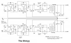
look at atached schm ;
we can go backwards ;
needed volatge is set with reference Led voltage ( 1V93 for green led at 5mA ) + Vbe of darlington (around 1V35) ;
so - for 24 V you'll need (24-1,35)/1,93 number of leds ...... and that's certainly nice thing to use round number , just because Leds certainly aren't practical to cut
 ......... so - we can use 11 leds and be in ballpark with ~ 23V ;
 exact voltage isn't critical , and all leds aren't the same , so you can expect that as rough target.
certainly for different voltages you can use red or yellow (even blue leds ) but I can leave to you to find what their working voltages are
")
I like round number of 5mA through led chain ; that's also current which is available at base of darlington ;
so - R10 is Ube/5mA =1V35/5mA=270E (it's always the same , no matter what number of leds/output voltage you have )
current through Q1/Q2 CCS combo is set by Vbe of Q1 ;
say that you need 20mA for load ( your gain stage ) ; goal is to have at least same amount of current burned in shunt element , in this case darlington ; but - that's sissy current , so I'll choose 50mA to burn through shunt , so overall current CCS need to push is 20+50mA , so R8paralleled with R9 ( that can be just one resistor , if power is adequate and value is near standard ) shall be Ube/Iccs=0V675/70mA=9E64 ( now you can mix two of them to achieve that value ) , with dissipation in it P=I^2 x R=70mA^2 x 9E64=0,05W , so you can use any 0,25W resistor there;
we need 24V on output ; say that nice voltage across CCS is at least 7V ( mosfet and surrounding parts needs almost 5V across to be functional) , so IC2 must be set for 24+7 Volts on it's output ;
LM317 -ref voltage is 1V25 ;
output voltage is : 1,25Vx(1+R3/R4) ;
you have ref voltage between output and adj pin of LM317 ; with 180E for R4 we have current through that resistor of ~7mA and that is enough , counting that we have significant amount of current going to CCS ;
so - output of IC2 is 11V25(1+4700/180)=33V9 ; feel free to alter R3 to have min 7V +24V on output
7mA^2 x 4700 is dissipation through R4 ;place double-power(ed?) resistor in that place
do not alter values of R1 and R2 ; with them - preregulator stage (IC1) is set to have it's output exactly 1V25(1+R1/R2) =4V5 above IC2 output
so - output of IC1 will sit on 33V9+4V5 =38V4
you need to calc on -10% voltage on mains , and you need -say - 4V5 across IC1 to behave ......... so - you need (38V4+4V5)x1,1 =47V on input of IC1
hehe ...... shunt regs are waste of voltage and current and temperature ........ but I like them
dissipation calcs are easy - mark voltage at each point - before and after IC1 , IC2 , then just multiply with current through each stage , then substract all dissipations ;
IC1 : (47V-38V4)x(7mA+7mA+5mA+20mA+50mA) = W
IC2 : (38V4 - 33V9 ) x (7mA+5mA+20mA+50mA)=W
CCS: (33V9-23V)x(5mA+20mA+50mA)=W
Q3 :23Vx50mA=W
clear enough ?
for other parts ( diodes and caps around LM317 ) - find datasheet for 317 and read
edit :
sum of 3W of dissipation ......... nice piece of sheet Al is sufficient to cool down everything
Attachments

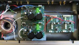
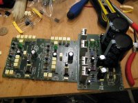
Rodeodave said:Choky, you're the best.
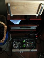
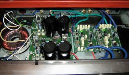
I'll post some pics of the twins when they are done.
What do you think of Christer's measurements?
what can I think , when good job is done ..................
Good Job !
(you owe me half a page of writing for that previous post of mine ....... either on French or on Italian ..... your choice
)Shinyy
symm Shiny , drawn for D1 , in another thread
http://www.diyaudio.com/forums/showthread.php?postid=1597703#post1597703
symm Shiny , drawn for D1 , in another thread
http://www.diyaudio.com/forums/showthread.php?postid=1597703#post1597703
Attachments
Master ZenMod, thank you for sharing your knowledge.
Your explications are very clear and very easy to understand (even for me!!).
I've made an excel spreadsheet that follow your formulas, I hope that it can be helpful for other newbies like me...
Olny a question: in general, if output voltage precision is needed, is correct to fine tune the LED's current (R10) to trim?
Guido
Attachments
GuidoR said:Master ZenMod, thank you for sharing your knowledge.
Your explications are very clear and very easy to understand (even for me!!).
I've made an excel spreadsheet that follow your formulas, I hope that it can be helpful for other newbies like me...
Olny a question: in general, if output voltage precision is needed, is correct to fine tune the LED's current (R10) to trim?
Guido
next time - be sure to include some funny smiley , when you call me a master
anyway .... in this moment I'm sorta low in energy , flue is just massacring me , even without temperature ..... I feel every bone in my body ( alas , that isn't so bad , remembering sometime how many bones we have
)so - I can't check your xls file , but I can say thank you
reason why led's are there , besides pretty good TempCo and low noise , iis pretty good voltage stability , regarding current variation ;
if you need slight voltage correction , just use some one or more leds with other color ; red ones have slightly greater characteristic voltage , so - you can try with any combination and number of red/blue/green/yellow .....
I hope I wrote something new to you .....


Zen Mod said:post this picture
Rumor has it that his cookbook "Gore-Man cuisine with anything that moves" was a bestseller in prisons of some parts around the globe.
jacco vermeulen said:
Rumor has it ....
... what's up with my dark blinkies , ya dutchy fenstermacher ?
- Status
- This old topic is closed. If you want to reopen this topic, contact a moderator using the "Report Post" button.
- Home
- Amplifiers
- Pass Labs
- another local NS10 & Shiny