Zen Mod said:so , cviller - anything new ?
( I'm ready for another public humiliation )

Hmm, very worried Choky.- Bad sign

Magura
Magura said:
Hmm, very worried Choky.- Bad sign
Magura
naah
just sleepless ........
cviller said:Yes, kinda... I bought a house
On the drek front, not much have happened. I have matched my 2sk369's and mailed a pcb set to lykkedk, so I guess we'll hear something from him during the weekend...
Yeah, let's wipe it off on Lykke
Magura
EDIT: Oh and congratulations
A house ought to make DIY easier, and it sure does. Unfortunately most people experience more space as an opposite linear function of time available for DIY efforts

Rob Dingen said:...........
Which choke do you use?
Why use a neg supply if you connect the choke to ground you can skip the output caps.
Rob
Choke is Magura-san's creation ; I'm sure that he'll chip in and say more ;
regarding secoond question - per Magura-san's wish , there is substantial current going through output stage(s) , and choke always have some Rdc , so , offset can't be negligible , either - in case that you ground center tap .
On the drek front, not much have happened. I have matched my 2sk369's and mailed a pcb set to lykkedk, so I guess we'll hear something from him during the weekend...
Whoo... looking forward to recieve that package CViller...
I think, if possible that some (Magura?) could tell howto make those choke's for the Drek. Just a thumbrule would be good... I was thinking of inner-size / outher-size and ~widht, and ofcause coil size (awg / mm.) ... And what is best regarding DC-resistance (small or thick Cu. wire ?) ... I think that not many know howto actually finish this Drek because of them coils... So mr. 'X' (Magura?) .. could you perhap's help us a little here
Also (Correct me if i am wrong please!) ... The hole idea about using a choke for the Drek, is to have a constant current supply for the fet's/jfet's. The coil/inductor, has the capabillity to hold on, and spit out, some currency, when circuit need it... like a sort of current accumulator/buffer.
Jesper.
Well this is not a inductor-design thread ... but i found this LINK! which i found very interesting. I tried to wind up, and old ''1mH 1mm 0,49 Ohm'', and the inductor-calculator was calculating very near that coil.
So... my quiston is now, if i should go for thick >=1mm or thin <=0,6mm Cu wire ??? The DC-resistance goes up, when wire gets thinner.
I would sure like to know, if 120mH with 1mm wire (6 ohm) is better than 160mH with 0,5mm wire (26 ohm) ... Hope someone could help me out, with a little explanation.
As Magura told me, some day's ago, i should just wind up two inductor's in one, so that i have two let's say 0,49mm. wires laying aside in that form.
The trick when calculating using that link, is to just double the length(please see, where length is messured on link) of the coil, and use the same number of turn's for getting two inductors in one.
Jesper.
this is not a inductor-design thread ... but i found this LINK! which i found very interesting. I tried to wind up, and old ''1mH 1mm 0,49 Ohm'', and the inductor-calculator was calculating very near that coil.So... my quiston is now, if i should go for thick >=1mm or thin <=0,6mm Cu wire ??? The DC-resistance goes up, when wire gets thinner.
I would sure like to know, if 120mH with 1mm wire (6 ohm) is better than 160mH with 0,5mm wire (26 ohm) ... Hope someone could help me out, with a little explanation.
As Magura told me, some day's ago, i should just wind up two inductor's in one, so that i have two let's say 0,49mm. wires laying aside in that form.
The trick when calculating using that link, is to just double the length(please see, where length is messured on link) of the coil, and use the same number of turn's for getting two inductors in one.
Jesper.
lykkedk said:Well
So... my quiston is now, if i should go for thick >=1mm or thin <=0,6mm Cu wire ??? The DC-resistance goes up, when wire gets thinner.
I would sure like to know, if 120mH with 1mm wire (6 ohm) is better than 160mH with 0,5mm wire (26 ohm) ... Hope someone could help me out, with a little explanation.
............
that really depends of your goals ...... what's the current through coil , what are losses you can allow .
for Drek - 160mH is certainly better than 120 is certainly better than 12 is certainly better than 1,2 is certainly better than 0,12 is certainly better than 0,012 is certainly better than 0,0012 is certainly better than 0,00012 is certainly better than 0,000012
Well, i allready know that 160mH is better than half, but when looking at schmatics i can't tell how much current, that will flow through them. Actually i would like to know, the benefit of having small/large (high R or low R) in thoose chokes in this circuit.
Making a 160mH dualcoil with 0,25mm wire is much easier than doing it with 1mm wire. So what's the deal regardingn thickness/Resistance ?
Jesper.
Making a 160mH dualcoil with 0,25mm wire is much easier than doing it with 1mm wire. So what's the deal regardingn thickness/Resistance ?
Jesper.
lykkedk said:Well, i allready know that 160mH is better than half, but when looking at schmatics i can't tell how much current, that will flow through them. Actually i would like to know, the benefit of having small/large (high R or low R) in thoose chokes in this circuit.
Making a 160mH dualcoil with 0,25mm wire is much easier than doing it with 1mm wire. So what's the deal regardingn thickness/Resistance ?
Jesper.
Resistance is only a matter of heat/loss. As loss is diminishing low in a pre, heat is the factor to be aware of.
The party begins at 0.25mm wire, where it ends is up to your wife
I tried just for kicks to run a pre, using the inductors I made for power amps. Those have a DCR of like 0.25.
The inductance is as Choky just said, 2*80mH per channel.
I did not forget you Lykke, but I have not stumbled on the data of the inductors I made for Steen/Cviller. To tell you the truth, I think I folded the paper in question, into a nice round ball and aimed for the bin
Magura
Magura said:
To tell you the truth, I think I folded the paper in question, into a nice round ball and aimed for the bin
ah, you mean you filed it into round folder
not sure if joke isn't lost in translation, but Choky will understand:pospremio ga u okrugli registrator
bays_9a5tt said:
.......
pospremio ga u okrugli registrator
certainly
crazy danske metal boy .......
Magura:
Resistance is only a matter of heat/loss. As loss is diminishing low in a pre, heat is the factor to be aware of.
Well if heat is the thing, i will make my inductor's somewhere between 0,40mm - 1,00mm thickness to avoid to big resistance.
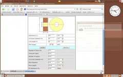
I took a scr.shot, of what i had in mind... The coillength will just double when winding two inductors in one (2x120mH)
Does it look ok?
Jesper.
Attachments
lykkedk said:
Does it look ok?
Jesper.
No, the number is 2*80mH
0.49mm wire is somewhat big for this, you may run into WAF problems.
Magura
bays_9a5tt said:
ah, you mean you filed it into round folder
pospremio ga u okrugli registrator
Yes, and it's been a while since it was filed there
Magura
I would just like to say, and anyone please correct me if I'm wrong, that there are some criteria I don't see suggested here regarding using the inductor in a coupled mode (differentially w/centertap). Just as when using a cap, when the signal frequency gets close to the freq that Xc developes a substantial value, phase shift, distortion and other subjectively bad things begin to appear. This is why you see coupling caps with a value that ussually creates an F3 low at about 2-2.5Hz. That is 3-4 octives below almost all the signal(music).
So, I would expect someone to realize, that when you are using an Inductor, you need to design for 2.5Hz Xl creating an F3 low or the music will be effected by the phase shift and other bad things.
Also, consider that in a differential circuit, you could treat your inductor as 1 big long inductor. The only current in the centertap should be DC not signal. So, if you plug in the whole length of the inductor into your calculator, rather than only one side, you will 4 times the Xl. That can be percived as 1/2 the Xl for each side of the differential.
All this basically means is a really big inductor. Take a look at what you can get from the hollow state world with enough DC capability
So, I would expect someone to realize, that when you are using an Inductor, you need to design for 2.5Hz Xl creating an F3 low or the music will be effected by the phase shift and other bad things.
Ok... as i see it, the inductor must be a low F3 (~2,5Hz) like size am i right, and how can i tell, when i calculate my inductor ?
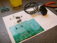
Cviller i recieved my package today, thank's for being so quick, especially thinking that you are occupied in house painting etc... How are you proceeding there ? good i hope!
I have attached a picture, and top-right is a DIY-counter, made by part's from pedometer, and rpm-controller from some crane
I will have to use it for winding inductor, when i have figured the right size.Jesper.
Attachments
lykkedk said:
Ok... as i see it, the inductor must be a low F3 (~2,5Hz) like size am i right, and how can i tell, when i calculate my inductor ?
Jesper.
As long as F3 is down around 18-20Hz, it makes no difference with most speakers, as they don't play lower than 25Hz, and even at 25Hz the distortion would be real hard to hear IRL.
Magura
I stumbled around the net, to find an explanation and to figure out, what Xl, inductance (mH) means to appr. coilsize / magnetwire thickness. And i didnen't succeded
I don't know how much current that will flow in drek inductor, and i don't know howto calculate the F3 of some inductor.
I have the possibillity to use magnetwire in the range 0,25 ~ 1,00mm, but if DCrestiance ain't the problem, i rather use thin, than thick.
I could make inductor's in size between ~80mH - 200mH, but what i really like is to understand, and to calculate the perfect size for the circuit.
Hope some (Magura, ZenMod etc...) can help me out!
Jesper.
- Status
- This old topic is closed. If you want to reopen this topic, contact a moderator using the "Report Post" button.
- Home
- Amplifiers
- Pass Labs
- The Drek builder's thread