Well here is my F5, i actually built this for a friend last year which he has been running all this time no problems to my excitement he told me he wants to upgrade and buy something he can have insurance on so we went looking for amps and so far he has decided on a couple of "class-A" Accuphase amps lucky bugger!
anyway this was my third Nelson Pass amp and definitely the best sounding, although the Zen V4 sounded great too! this F5 beats it for me.
This was before we connected the speaker Terminals and LED up

Light Bulb for testing the PSU, I wanted to be safe

My only regret is that the boards I used were from ebay, perhaps it would have been wiser to get the more expensive but authentic boards. it was a money thing!

Heres how i wired the caps up on strip-board I think

Originally applied too much thermal paste, started again took layers off the mica so that the mica was very thin, then added minimal paste. worked wonders on the heat transfer!
before then i had no idea you could split the mica with a sharp knife

In total I think it cost us about £300-350 to make im buying it back off him for £200 which is nice") i shall enjoy the sound when it arrives back here.
i shall enjoy the sound when it arrives back here.
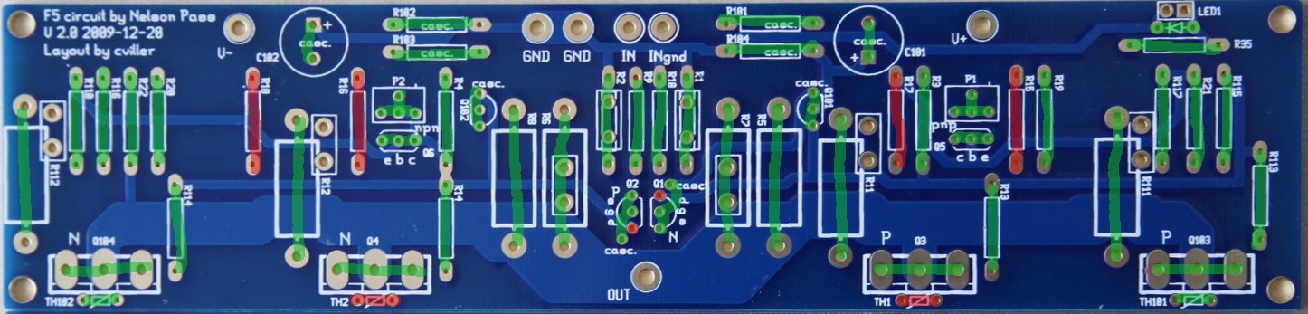
I do have one question, there are capacitors on my board! but none on the original F5 any comments on that ?
Well There we go, if theres anything you think i could improve on let me know thx
anyway this was my third Nelson Pass amp and definitely the best sounding, although the Zen V4 sounded great too! this F5 beats it for me.
This was before we connected the speaker Terminals and LED up
Light Bulb for testing the PSU, I wanted to be safe
My only regret is that the boards I used were from ebay, perhaps it would have been wiser to get the more expensive but authentic boards. it was a money thing!
Heres how i wired the caps up on strip-board I think
Originally applied too much thermal paste, started again took layers off the mica so that the mica was very thin, then added minimal paste. worked wonders on the heat transfer!
before then i had no idea you could split the mica with a sharp knife
In total I think it cost us about £300-350 to make im buying it back off him for £200 which is nice
i shall enjoy the sound when it arrives back here.I do have one question, there are capacitors on my board! but none on the original F5 any comments on that ?
Well There we go, if theres anything you think i could improve on let me know thx
Last edited:
Nice looking amp.
They are non-approved boards... That kinda explains it.
.
BTW, I'm listening to some of your music on your site, I really like 'Popfunk'
I do have one question, there are capacitors on my board! but none on the original F5 any comments on that ?
They are non-approved boards... That kinda explains it.
.
BTW, I'm listening to some of your music on your site, I really like 'Popfunk'
Last edited:
i had nothing to to with the design. i only gave him the calculation for the cascoding resistors. this is the same boards that i have. but my Boards are not cascoded.
Thanks again Audiosan ! My boards are the ones shown in this cviller-guide: http://www.diyaudio.com/forums/blogs/cviller/191-gb-f5-guide-pcb-version-2.html which even had a careful explanation of all options.
I just did not notice anyone actually building some of these...
If you assisted in the cascode design... Any reason the O/P pair was not cascoded ?
Nice looking amp.
They are non-approved boards... That kinda explains it.
.
BTW, I'm listening to some of your music on your site, I really like 'Popfunk'
Yeah, i might get the proper boards, but then un-soldering the components and putting them on the new board is a bit time consuming, could just buy some new components, decisions decisions
which board would u recommend ?
i expect it wouldnt be safe to remove those caps lol
you like my song, thanks!
i have lots more music to put up there when i get round to it!, also think ill do some audiophile recordings some time, downloadable in wav
Last edited:
A question Iv'e had about the F5 for some time
Do you think it would be possible to have some kind of Bias adjustment so that i can put the amp in power saving mode for low listening levels, then hit the bias on full if i turn the music up ? either variable or switched bias. how easy do u experts think that would be to do ?
Also i don't have a pre-amp and use mainly the computer for volume, has anyone else just attached a volume to the amp ? or are u all using pre-amps
Do you think it would be possible to have some kind of Bias adjustment so that i can put the amp in power saving mode for low listening levels, then hit the bias on full if i turn the music up ? either variable or switched bias. how easy do u experts
think that would be to do ? Also i don't have a pre-amp and use mainly the computer for volume, has anyone else just attached a volume to the amp ? or are u all using pre-amps
Yeah, i might get the proper boards, but then un-soldering the components and putting them on the new board is a bit time consuming, could just buy some new components, decisions decisions
Nah, that would open a can of worms. Just get approved boards for the next one.
Do you think it would be possible to have some kind of Bias adjustment so that i can put the amp in power saving mode for low listening levels, then hit the bias on full if i turn the music up ? either variable or switched bias.
The F5 is one big balancing act... that might upset the balance in weird ways... I wouldn't do it, but would be interested in seeing what the smart people have to say about it.
Also i don't have a pre-amp and use mainly the computer for volume, has anyone else just attached a volume to the amp ? or are u all using pre-amps
Works fine. You might not have enough gain, depending on your soundcard or headphone jack, but that's easy enough to test, and if you find you need a bit more gain, quite easy to change in the F5.
Nah, that would open a can of worms. Just get approved boards for the next one.
The F5 is one big balancing act... that might upset the balance in weird ways... I wouldn't do it, but would be interested in seeing what the smart people have to say about it.
Works fine. You might not have enough gain, depending on your soundcard or headphone jack, but that's easy enough to test, and if you find you need a bit more gain, quite easy to change in the F5.
Thanks, With the Zen v4 i did make a switch that would change the value of the bias resistor. In on position is added another resistor in parallel with the bias one to give it full value. it seemed to work well, hitting the switch produced a very small audible click but seemed harmless .
But i see F5 i remember now the bias is kind of auto biasing with thermistors and a bit more complicated.
About the volume, what i meant with that is, i use computer for volume but realy it would be better to have the computer volume level set to max and build a volume into the amp ? apparently digital sounds worse the lower the output from soundcard.
also if i accidentally unplug/nock the jack lead to the amp from my laptop (source) when its on it will probably give a very loud buzz on the speakers.
For anyone wondering the F5 is loud enough without a pre-amp connected to the average computer sound card, Iv'e not tested CD-players yet
Thanks for your help
Last edited:
i had nothing to to with the design. i only gave him the calculation for the cascoding resistors. this is the same boards that i have. but my Boards are not cascoded.
Allright, Audiosan. So my quest remains: Has anyone actually built cvillers ver.2 in the cascoded option ?
Since you calculated the resistors, do you have an idea of the values for C101/102 ? They are absent from the BOM. But clearly actached to the cascoding transistors/resistors. (Ironic really, Mr. Pass made a point of avoiding capators...;-)
i had nothing to to with the design. i only gave him the calculation for the cascoding resistors. this is the same boards that i have. but my Boards are not cascoded.
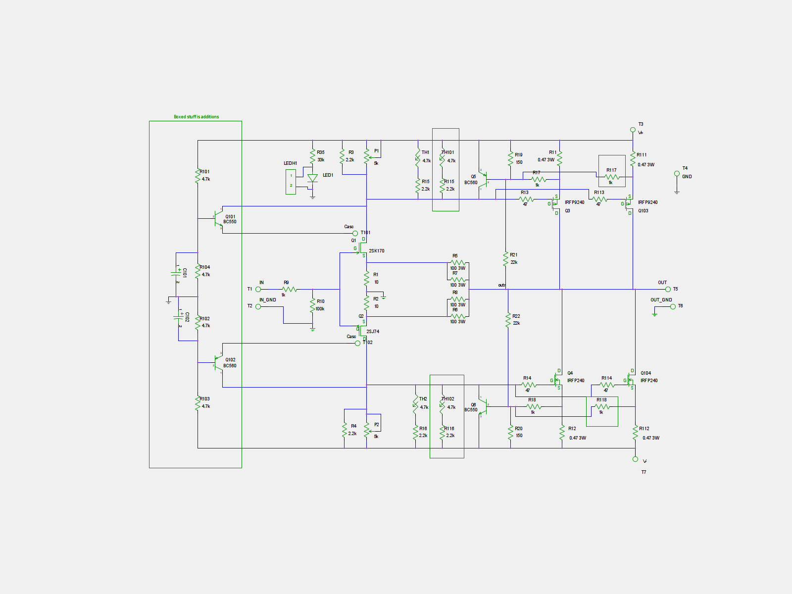
Sorry, me again, regarding cascoding resistors. I just noticed that the diyAudio store F5c (based on cviller design, but new board) changed the schematic for these voltage deviding resistors.
Your design was 4K7 for R101 thru 104.
They changed it to 10 ohms for R 101 thru 104 ! That's gotta be an error !
Why pull 1 amp just for the bases of the cascode resistors ?
I guess I should stick to 4K7, right ?
(They also made the emitter resistors in half without changing the current sensing circuit. So now these limit at 20 amps for EACH O/P device....).
(I should say at this point that I dont want to use dual parallel O/P devices in my build, just the input cascoding which I expect will help to reduce distortion. I learned long ago that it is difficilt to parallel semiconductors. The hottest one will carry the load. Unless you use large emitter resistors, which is not were you wanna move).
Schematics in the attachment and here:
http://www.diyaudio.com/forums/blog...5-guide-pcb-version-2-f5_cascode_forguide.png
Attachments
Allright, Audiosan. So my quest remains: Has anyone actually built cvillers ver.2 in the cascoded option ?
Since you calculated the resistors, do you have an idea of the values for C101/102 ? They are absent from the BOM. But clearly actached to the cascoding transistors/resistors. (Ironic really, Mr. Pass made a point of avoiding capators...;-)
you can use 10-47uF for those caps. regarding the resistors, the value depends on the rail voltage. if all 4 resistors are of the same value, the voltage will be little under half of the rail voltage.
Sorry, me again, regarding cascoding resistors. I just noticed that the diyAudio store F5c (based on cviller design, but new board) changed the schematic for these voltage deviding resistors.
Your design was 4K7 for R101 thru 104.
They changed it to 10 ohms for R 101 thru 104 ! That's gotta be an error !
Why pull 1 amp just for the bases of the cascode resistors ?
I guess I should stick to 4K7, right ?
(They also made the emitter resistors in half without changing the current sensing circuit. So now these limit at 20 amps for EACH O/P device....).
(I should say at this point that I dont want to use dual parallel O/P devices in my build, just the input cascoding which I expect will help to reduce distortion. I learned long ago that it is difficilt to parallel semiconductors. The hottest one will carry the load. Unless you use large emitter resistors, which is not were you wanna move).
Schematics in the attachment and here:
http://www.diyaudio.com/forums/blog...5-guide-pcb-version-2-f5_cascode_forguide.png
it's no problem running dual outputs. and there are no need for cascoding with +/-23V rails. only when you have around +/-30V and up. and for that, you will need dual outputs. otherwise you will destroy your outputs. unless you plan on running it with low bias.
Last edited:
it's no problem running dual outputs. and there are no need for cascoding with +/-23V rails. only when you have around +/-30V and up. and for that, you will need dual outputs. otherwise you will destroy your outputs. unless you plan on running it with low bias.
As I understand it, cascoding also has other advantages, wrt. reducing distortion, than just beefing up the voltage, as Mr. Pass explains here: http://www.passdiy.com/pdf/articles/cascode.pdf
Tranny at 22V secondaries
Hi,
I have just finished my F5 amp and I am very excited how it sounds. It is awesome!!
But I have a little hiccup .... I used a 300w 22V dual secondaries I had on hand ( searched the forum and I found that it was right to use it but at the high point limit) and with the Universal power supply and 44000 uF each channel capacitance gives roughly +- 30 Volts. With this psu voltages and the recommended bias of 0.59 volts across R11 and R12, the temperature of the heatsink is 55 C and the bolt securing the output transistor is at near 110 C. I am worried if I am going to fry the output transistors or something else.
I have bought a 18 V dual sec tranny rated at 500 W but I am still waiting for it.
Maybe I have to reduce bias in my actual setup? Or is it wrongly set the bias and one transistor is working harder than the other in the same channel?
Thank you all and sorry for my English...
Jorge
Hi Jorge
55C difference between bolt and the sink means either your sink base is too thin or you have improper mounting. At 40W dissipation 55C delta temperature means ~1.4C/W between device and sink surface, which is extremely high. A good mount should not be more than 0.4, an excellent mount can be as little as 0.2.
Can you post a picture of the setup?
Thank you
Hi,
As I understand, due to the higher voltages of my psu, the bias adjustment should be lower. The value stated of 0.38 is obtained from?
Thank again for your support, I appreciate.
Best
Jorge
Jorge, I would reduce the bias to about 0.38 for now if I was you.
Hi,
As I understand, due to the higher voltages of my psu, the bias adjustment should be lower. The value stated of 0.38 is obtained from?
Thank again for your support, I appreciate.
Best
Jorge
Hi Jorge
55C difference between bolt and the sink means either your sink base is too thin or you have improper mounting. At 45W dissipation 55C delta temperature means ~1.2C/W between device and sink surface, which is extremely high. A good mount should not be more than 0.4, an excellent mount can be as little as 0.2.
Can you post a picture of the setup?
Hi,
I have some photos but I am afraid I have to learn how to upload them....
For now, my case is a HiFi 2000 Pessante Dissipante 3U. And the channel boards are in the middle of each heatsink.
I will post photos soon, thank you all folks...
All the Best,
Jorge
the "standard" F5 has an idle current of around 1.3A when biased at 0.6V on a 23V rail. The power dissipated is 30W through each FET.
These are rough numbers but if you worked on the power dissipated you could bias at 0.47V which will be 1A through 0.47ohm.
I suggested 0.38V as it still gives you reasonable class A performance for now. After you have some more mileage (hours) on your new amp and have sorted out the thermal coupling and the corrected rail voltage you can ramp it up again.
Its a value I played with in the begining and the sound was still great. Only a suggestion...
Last edited:
Thank you... Again.
Hi,
Thanks again for the info. I thought erroneously that increased rail voltages did not affect too much to the bias setting. And as I learn from all of you and also from experience (I work in a office and this is a hobby along with 3 kids.... ) I wanted to know where was obtained.
Best,
Jorge
the "standard" F5 has an idle current of around 1.3A when biased at 0.6V on a 23V rail. The power dissipated is 30W through each FET.
These are rough numbers but if you worked on the power dissipated you could bias at 0.47V which will be 1A through 0.47ohm.
I suggested 0.38V as it still gives you reasonable class A performance for now. After you have some more mileage (hours) on your new amp and have sorted out the thermal coupling and the corrected rail voltage you can ramp it up again.
Its a value I played with in the begining and the sound was still great. Only a suggestion...
Hi,
Thanks again for the info. I thought erroneously that increased rail voltages did not affect too much to the bias setting. And as I learn from all of you and also from experience (I work in a office and this is a hobby along with 3 kids....
) I wanted to know where was obtained.Best,
Jorge
- Home
- Amplifiers
- Pass Labs
- F5 power amplifier