
In the F5 turbo manual, there's another F5 circuit with a couple new changes. The resistors on the input which are R1 & R2 on that schematic are 4.75K and 47.5K and they're configured differently. Also TH1 & TH2 don't go to the rails anymore. And P3 was added. Supposed to be subtle differences. Far as I know the latest circuit is the one in the F5 Turbo manual.
I would use the latest parts values and make the changes. But not absolutely neccessary.
I would use the latest parts values and make the changes. But not absolutely neccessary.
Hello fellas, today i bought 4 pcs. 20V 6A "toroid international" transformers from a surplus store, nearly for free. ($4 each)
Since a long time, i have been planning an F5 and i had nothing but a pair of big nice heatsinks in hand, that could be used for F5 with a little active cooling support. I thought that these trannies (480VA total) could be used for F5 too, and today i re-read the F5 datasheet and it looks like Pass recommends betveen 23-25 volts per rail.
The new transformers have 20V secondaries and it makes about 26,5-27,5 after the rectifier bridge with no load. I wonder would it be safe to use these trannies or should i use something at 25VDC (18VAC) sharp?
Last edited:
What PSU configuration are you using? If you're going with the standard Pass CRC, I'm guessing you might have enough losses to get closer to the 25VDC level between the rectifiers, caps, resistors, thermistors, and the drop that comes with load. You could also slightly increase the R in CRC if you're close but not quite there.
20V 6A "toroid international" ($4 each)
From now on I'll call you XtraFixxxxxer.
Hello fellas, today i bought 4 pcs. 20V 6A "toroid international" transformers from a surplus store, nearly for free. ($4 each)
Since a long time, i have been planning an F5 and i had nothing but a pair of big nice heatsinks in hand, that could be used for F5 with a little active cooling support. I thought that these trannies (480VA total) could be used for F5 too, and today i re-read the F5 datasheet and it looks like Pass recommends betveen 23-25 volts per rail.
The new transformers have 20V secondaries and it makes about 26,5-27,5 after the rectifier bridge with no load. I wonder would it be safe to use these trannies or should i use something at 25VDC (18VAC) sharp?
Based on my personal build
F5 standard with no mods can handle that easy I am using 24 V AC 1000VA trafo so they drop less than yours would
is all down to how big your big heath sinks are.
looking at your Signature keep in mind that is much colder here than where you hare and we use the F5 to help the central heating system
The J fet can handle up to 35 V dc I tried and chiken out at that
For peace of mind ad another RC stage
I did more for further riple reduction than else
Still cascoding can do no arm and is easy done
Last edited:
Thanks everyone for the explanatory answers! It seems like it's completely safe to use the trannies witthout any modifications, especially depending on the experiences of @sangram & @Bksabath:
@oneplustwo; i'll probably go with the standard CRC as you told. i'll keep adding extra resistance in mind, in case of an inaccuracy in the voltage.
@6L6; thanks for the recommendation. i searched but couldn't find anything about a cascode version. as i mentioned, i'll probably use the transformers and psu circuit unmodified, but a link for that would be nice for future reference. could you please post if you have?
@jacco vermeulen; thanks") it was a real lucky deal indeed.
it was a real lucky deal indeed.
I used 22V, 400VA transformers on each channel of an F5 and had 27.5 V at the rails with full load (closer to 29V with no load). The amp ran fine at that voltage. Stock F5 except 2x the recommended supply capacitance.
Based on my personal build
F5 standard with no mods can handle that easy I am using 24 V AC 1000VA trafo so they drop less than yours would
is all down to how big your big heath sinks are.
looking at your Signature keep in mind that is much colder here than where you hare and we use the F5 to help the central heating system
The J fet can handle up to 35 V dc I tried and chiken out at that
For peace of mind ad another RC stage
I did more for further riple reduction than else
Still cascoding can do no arm and is easy done
What PSU configuration are you using? If you're going with the standard Pass CRC, I'm guessing you might have enough losses to get closer to the 25VDC level between the rectifiers, caps, resistors, thermistors, and the drop that comes with load. You could also slightly increase the R in CRC if you're close but not quite there.
@oneplustwo; i'll probably go with the standard CRC as you told. i'll keep adding extra resistance in mind, in case of an inaccuracy in the voltage.
You could build F5Cascode version, to better handel the additional voltage.
@6L6; thanks for the recommendation. i searched but couldn't find anything about a cascode version. as i mentioned, i'll probably use the transformers and psu circuit unmodified, but a link for that would be nice for future reference. could you please post if you have?
From now on I'll call you XtraFixxxxxer.
@jacco vermeulen; thanks
it was a real lucky deal indeed.@6L6; thanks for the recommendation. i searched but couldn't find anything about a cascode version. as i mentioned, i'll probably use the transformers and psu circuit unmodified, but a link for that would be nice for future reference. could you please post if you have?
Just look for F5c and you will find a cascode version. The diyaudio store carries the boards diyaudio store and there is a really detailed build thread recently F5c Build Documentation.
The store is unfortunately out of boards for the F5c at the moment though. It has double the output transistors for double the power, but can be run with just a single pair for normal power.
Hello,
Here's my experience with trying out different feedback values.
I made an F5 with reduced feedback, I used 75 ohm instead of the normal 50 ohm, on my old speakers it sounded very good.
But now on my new speakers I found the bass not tight enough and the voices not clear enough, it was like seeing two the same images on top of each other that are shifted, so it looks a little blurry.
I changed the feedback value to 50 ohm and now it sounds much better: tight bass, clear voices, larger soundstage, more detail, you get better the feeling of "being there", definitely much better for me than the 75 ohm FB.
If you find the F5 better sounding with reduced FB you should first look at your speakers and adjust the voicing a little: add more bass by adding a resistor of 1-2 watt before the mid/highs (very easy to do if the speakers have separate binding posts for bass and mid/highs).
Regards,
Danny
Last edited:
ianc13 and 6L6 :
I am glad this topic of cascoding re-appears.
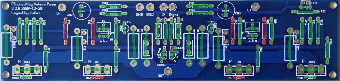
I have cvillers ver.2 PCB boards of 2009-12-20.
I purchased parts for the cascoded version using BC 550/560.
However, it seems nobody built this ?
The only cascodes I was able to find use diyAudio's boards.
I would appriciate some pics of the cviller ver.2 cascoded build, since the board population seems a bit confusing.
I am glad this topic of cascoding re-appears.
I have cvillers ver.2 PCB boards of 2009-12-20.
I purchased parts for the cascoded version using BC 550/560.
However, it seems nobody built this ?
The only cascodes I was able to find use diyAudio's boards.
I would appriciate some pics of the cviller ver.2 cascoded build, since the board population seems a bit confusing.
have you read Cviller's F5 build guide?
Thanks Audiosan, yes I did.
Cviller explicitly states he did not try the cascode of the ver.2 PCB boards, dating 2009-12-20.
(It IS somewhat confusing that also the diyAudio PCB boards are named "ver.2", but it seems that members prefer to call these boards "F5c turbo")
i gave Cviller the recipe for the cascoding. and he have publised that in the F5 guide.
i'm not sure what your Boards look like. can you take a pic of them?
Thanks again Audiosan ! My boards are the ones shown in this cviller-guide: http://www.diyaudio.com/forums/blogs/cviller/191-gb-f5-guide-pcb-version-2.html which even had a careful explanation of all options.
I just did not notice anyone actually building some of these...
If you assisted in the cascode design... Any reason the O/P pair was not cascoded ?
- Home
- Amplifiers
- Pass Labs
- F5 power amplifier