Are you asking about making a separate chassis for the power supply? Yes, it is a good idea.
Look for the 4-terminal "Speakon" connector from Neutrik to make the cable. Very nice!
Yes, that's exactly what I was thinking !! But....why?
And make a compact F5 also
")
RGDS
PEMO
F5 - modifying damping factor by lowering feedback
Hi all. Changing harmonics by regulating P3 is already widely known method of changing F5s sound. But what about changing amount of feedback? Papa gave us some hint in F5 Turbo article. There we have half the original feedback and overall distortion was still extremely low. Nelson described effects of this as "mellower" more "relaxing" sound.
What if we'd like to make feedback even lower? How low can we go?
If we look at SIT amps - on paper they go in similar direction:
much higher distortion and low damping factor. Also J2 and F3 are more in this direction when compared to original F5. I suppose that adjusting P3 for 2nd order harmonics AND lowering feedback could get us closer to J2 or F3 sound (or even SIT)
Have anyone tried it? What's the highest reasonable value of feedback resistors? (as for bandwidth - I'm ok with flat 20khz - don't need more)
Regards,
Kuba
Last edited:
But what about changing amount of feedback? Papa gave us some hint in F5 Turbo article. There we have half the original feedback and overall distortion was still extremely low.
Have anyone tried it? What's the highest reasonable value of feedback resistors? (as for bandwidth - I'm ok with flat 20khz - don't need more)
Yes, I have tried it. It works well.
Decreasing the feedback (more ohms in position R5, 6, 7, 8) also has the advantage of increasing the gain of the amplifier, and that is usually the reason people have changed it. I have used 150R in those positions, it sounds great. I know that others have used 220R with good results.
Lowering the gain by increasing the feedback even further will lead into insability (high frequency oscillations). I don't know the lowest possible feedback for this amp but at least according to simulations a total gain of 10dB is already on the worse side.
If you want to go that way, you would have to change the schematics to stay savely within the stable region. I did this in my headamp by increasing the R from the sources of the JFets to ground à la BA3 Frontend.
Best regards
Flo
If you want to go that way, you would have to change the schematics to stay savely within the stable region. I did this in my headamp by increasing the R from the sources of the JFets to ground à la BA3 Frontend.
Best regards
Flo
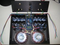
Is this a proper way of grounding my dual mono F5's?
something doesn't look right to me

You're making me curious...
Is it a good thing to twist the powerrail wires and GND wires going to the amp-board?
Or should I just twist the powerrail wires, and ground separate going to the board? Or twist nothing?
Is it wise to ground the sides of the chassis? Because the shielding / grounding is now going through a few bolds in the chassis. I don't like that.
Grz, Walter
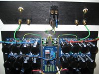
I do not follow how you are using the 2 bridge rectifiers in the grounding. Not sure if you could sketch. Also others have said not to connect the input grounds directly to the PSU board ground. I connected the PSU ground and the input grounds to the amp board ground pads.
A sketch would help, but it looks like you have two completely separate Main Audio Grounds (MAG), one to each channel.
Then you have used the bridge + components as a Disconnecting Network (DN) to give the Fault Current route back to Safety Earth.
If that is the case then you should be able to measure Left Ground to Right Ground as twice the resistor value you used in the DN. And each MAG to Safety Earth should measure the same as the resistor value.
And as a final check when you disconnect the DNs the MAG to MAG and/or MAG to Safety Earth should read open circuit.
Andrew that's correct.
The thermistors over the bridge rectifier are 5 ohm( actually when I measured them they are 7 Ohms, depends on temperature) and between the MAG's is 14.0 Ohm.
I read that you wrote a lot about this subject, do you think it is appropriate for the dual mono setup I'm trying to build? Or should I use separate earths for each amp?
@Bnorrish: I'm using the exact schematics as described in the F5 Turbo document from Nelson Pass.
Quote: "
Nelson uses only one PSU for both channels. I build two Turbo PSU's so I can upgrade to a F5 Turbo when the boards arrive at the DIYAudio store
The thermistors over the bridge rectifier are 5 ohm( actually when I measured them they are 7 Ohms, depends on temperature) and between the MAG's is 14.0 Ohm.
I read that you wrote a lot about this subject, do you think it is appropriate for the dual mono setup I'm trying to build? Or should I use separate earths for each amp?
@Bnorrish: I'm using the exact schematics as described in the F5 Turbo document from Nelson Pass.
Quote: "
As commonly seen in my previous projects, you will also see a thermistor /
diode bridge combination used to provide ground loop isolation between the
chassis, which is hardwired to the AC outlet ground, and the circuit ground.
An ordinary CL60 thermistor and a 35 amp rectifier bridge should suffice. "diode bridge combination used to provide ground loop isolation between the
chassis, which is hardwired to the AC outlet ground, and the circuit ground.
Nelson uses only one PSU for both channels. I build two Turbo PSU's so I can upgrade to a F5 Turbo when the boards arrive at the DIYAudio store
Walter -
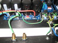
Use only one bridge as the resistance between chassis earth and audio ground... having two seems like it will only add a potential loop.
Take the speaker return (black or negative speaker connection) from the amp PCB, not the PSU - it's much quieter that way.
Also, if possible, please draw a schematic of your wiring, it will help us understand your connections.
Nice work, by the way - neat wiring, good layout, I'm looking forward to seeing more photos of your amp!
You're making me curious...
just couldn't see the two diode/bridge are used only for chassis/earth connection
I have never seen this
Walter -
Use only one bridge as the resistance between chassis earth and audio ground... having two seems like it will only add a potential loop.
Take the speaker return (black or negative speaker connection) from the amp PCB, not the PSU - it's much quieter that way.
Also, if possible, please draw a schematic of your wiring, it will help us understand your connections.
Nice work, by the way - neat wiring, good layout, I'm looking forward to seeing more photos of your amp!
6L6,
Running the ground from amp PCB to speaker and from amp PCB to power supply? How do you purpose RCA input ground be run? What happened to single point ground?
Rush
- Home
- Amplifiers
- Pass Labs
- F5 power amplifier