Thanks to all for the knowledge! I hit Radio Shack up on the way home from work so I can start experimenting right away. Some better parts from Mouser will arrive Friday.
I always wondered what the significance of fifteen watts in particular was. Silly of me to ignore the experimental possibilities all these years, a mistake I won't make again. Next year I should build another amp - but I don't need anything else.
I always wondered what the significance of fifteen watts in particular was. Silly of me to ignore the experimental possibilities all these years, a mistake I won't make again. Next year I should build another amp - but I don't need anything else.
Does anyone know of a distributor in the Netherlands that has mica insulators for TO-247 packages.
Your helpis very much appreciated!
Regards René
Ebay distributes everywhere!
Does anyone know of a distributor in the Netherlands that has mica insulators for TO-247 packages.
Your helpis very much appreciated!
Regards René
You can buy Kerafol (much better than mica insulators) from Conrad in Europe. Conrad - Uw online shop voor elektronica, computer, multimedia, modelbouw & techniek
Just type kerafol in the search box. You want the type with the highest "warmtegeleidbaarheid".
I have bought a 190mm x 190mm sheet and just cut the sizes I need with a pair of scissors.
Warmtegeleidende folie Keratherm - Rood 86/82 Kerafol 86/82 (l x b) 190 mm x 190 mm Dikte 0,25 mm 6.5 W/mK in de Conrad online shop
I always wondered what the significance of fifteen watts in particular was.
That should have been fifteen ohms, of course. I need to get more sleep.
Hello, who can inform me to find the F5 power supply pcb ?
Thanks.
The diyAudio store carries them, I'm not sure where you are located so shipping may or may not be a concern.
water cooling with two pairs
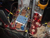
25V 4A/ch, dual outputs, thermistor circuit and current protection removed. All other resistor values are stock.
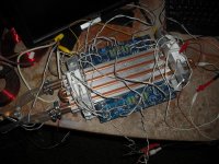
Somebody asked for some more pics of the PS, so here it is. 2 - 4.0mH paralleled per rail, and 1 - 2.7mH per rail. After about two hours, the 2.7mH 12ga coils have that burning enamel smell, which isn't too pleasant. 3 - 60V 47mF per rail, and a small group of C's (forget values) before going to the amp. Adding two more pairs of outputs definitely changed the character of the sound, for some reason I enjoyed the single pair version better, but I'll need to chill the incoming water If I want to increase bias on that one. I'll probably start by increasing the feedback resistors on this version...not much else to change.
-john
25V 4A/ch, dual outputs, thermistor circuit and current protection removed. All other resistor values are stock.
Somebody asked for some more pics of the PS, so here it is. 2 - 4.0mH paralleled per rail, and 1 - 2.7mH per rail. After about two hours, the 2.7mH 12ga coils have that burning enamel smell, which isn't too pleasant. 3 - 60V 47mF per rail, and a small group of C's (forget values) before going to the amp. Adding two more pairs of outputs definitely changed the character of the sound, for some reason I enjoyed the single pair version better, but I'll need to chill the incoming water If I want to increase bias on that one. I'll probably start by increasing the feedback resistors on this version...not much else to change.
-john
Attachments
25V 4A/ch, dual outputs, thermistor circuit and current protection removed. All other resistor values are stock.
Somebody asked for some more pics of the PS, so here it is. 2 - 4.0mH paralleled per rail, and 1 - 2.7mH per rail. After about two hours, the 2.7mH 12ga coils have that burning enamel smell, which isn't too pleasant. 3 - 60V 47mF per rail, and a small group of C's (forget values) before going to the amp. Adding two more pairs of outputs definitely changed the character of the sound, for some reason I enjoyed the single pair version better, but I'll need to chill the incoming water If I want to increase bias on that one. I'll probably start by increasing the feedback resistors on this version...not much else to change.
-john
What gauge are your inductors? I thought you were not supposed to use inductors in parallel in a power supply because it can cause problems.
The 4.0mH in parallel are 12ga. Connected in parallel there is less current through each, and less overall inductance. There doesn't seem to be any issues, maybe the fields from each inductor are interfering with each other, which is probably the case in my setup. I'd be interested to know what's taking place as well....but that sweet sound keeps getting in the way
Last edited:
I am working with F5 8 capacitors as mandated scheme, the pack I bought was 10 capacitors. I have 2 capacitors of 15,000 left over, and I was thinking PSU will plug them.
Where would better connect them together the first capacitors, or resistors after?
Connection blue or red connection?
thank you
Where would better connect them together the first capacitors, or resistors after?
Connection blue or red connection?
thank you
Attachments
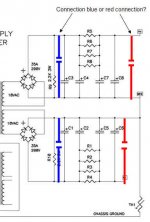
I am working with F5 8 capacitors as mandated scheme, the pack I bought was 10 capacitors. I have 2 capacitors of 15,000 left over, and I was thinking PSU will plug them.
Where would better connect them together the first capacitors, or resistors after?
Connection blue or red connection?
thank you
It is always better to reduce the first cell, even if this implies a larger ripple voltage, because the ripple current will be lower; ripple current being the cause for saturation of the transformer and adverse effects of the diodes.
I have a small first cell of not more than 3.000 muF. You can if you have caps left, easily make three cell banks.
Use your best capacitors after the R of the rCRC.
Ensure the caps before the R can take the ripple current that will be imposed on them.
Many smaller capacitors usually run cooler than a few big capacitors in this first C position.
Use cheap commercial caps for that first C. They are so far removed from the Audio Signal That comes later that they have virtually no effect on Audio Quality. But they MUST operate as capacitors for the first stage filtering rC to be effective. Fakes and undersized are no good here.
Back to the caps after the R:
These supply the LF current to the amplifier. They should be adequately sized to meet that LF current demand and they should be good for Audio. That does not mean they need to be exotic AudioPhool types, but they must be good capacitors that can release charge when demanded.
Last edited:
I would suggest Pnasonic FR
25V, 3300uf
can size 16x25mm, ESR 14 mohm(0.014)
very impressive 3.8A ripple current
buying 100 of them wouldn't cost much
but to mount and wire them all...
btw, where are the limits regarding lowering ESR and increasing current handling, by paralelling caps ?
(I suppose it takes other considerations than just simple math)
Gootee did a lot on this.btw, where are the limits regarding lowering ESR and increasing current handling, by paralelling caps ?
(I suppose it takes other considerations than just simple math)
Read his posts.
As Al, and Andrew said above
It's the ripple current ability that is the more significant characteristic of the first cap after the diodes, not just the size (or lack of it) but the Type and unfortunately, most audio related caps aren't specified with this information - however, you're looking for 'pulse caps' or caps that'll suffer quite severe current pulses without complaint - in the case of the F5, you're looking at charging current pulses well in excess of 15 Amps, so you're looking towards industrial type caps for this position and resistance to 'self resonance' that you get with the thicker film, lower etch foil types.
Luckily, these are now "out of fashion" with many audio people and there's a lot more around at reasonable prices but they are larger in size - unfortunately, even tho many people use the small Pana FRs, they aren't the best 'ripple' cap on the market - they are better at 2nd, or 3rd, cap in the chain.
The F5 amp is quite dependent of power supply caps for final sound and I'd suggest very good caps, as high as the budget allows.
... my 2 cents.
- Home
- Amplifiers
- Pass Labs
- F5 power amplifier