This implies it could be in that beautiful build you have . . .It vanished only when i short the right input...
Did anyone have additional ideas?
What about stray inductance in the connection to one board? How about increasing the gate stoppers? You could add at least a 1K resistor; the inherent feedback reduces the effect of the high capacity anyway. (I have increased it myself and added a trifle of a capacitor too . . ).
I assume the power supply is not the problem, being a usual suspect? I once had one channel noisier, came down to imbalance of the power supply caps in the first cell (measured 53.000 uF against 56.000 uF) - that is why I now have a very small first cell. In one channel I noticed it (on scope) .
In the Turbo f-5, Mr Pass states that he has increased gain to 22 dB by changing R7-R10 from 100 ohms to 220 ohms. Will this work the same way for the standard F-5? If so, this seems like a reasonable increase. Could the resistors just be changed to these values, 220 ohm, the amp re-biased and good to go? Or is this too much for a non-turbo F-5? Wish I wasnt so chicken, I'd just try it! Soon I will have a second F-5 and I will be a little braver! I have a few blank pairs of Daniels F-5 boards and would like to make this new one a little easier to change boards and so forth out in order to try such things without fear of being left F-5 less.
Russellc
Russellc
Has been stated and prooved several times, by ZenMod, Papa himself and a lot of other well-known and well-knowing persons, in this and in other threads, hard to find I know.
Just go for it!
No, I just mean for the value, 220 instead of the 100. Didnt know if this value was specific to T-F5 0r would also be a good value for standard F5...
Russellc
No, I just mean for the value, 220 instead of the 100. Didnt know if this value was specific to T-F5 0r would also be a good value for standard F5...
Russellc
In the beginning, Nelson proposed to take out one of the 100R on each half to get a feedback of 100R instead of 50R and increase the gain by approx 6dB. With two times 220R in parallel on each half the feedback will be 110R... Nothing to worry about.
I think you could even go higher, get even more gain (and a more stable circuit) but the distortion will be worse.
Thanks for the input, I was in on one of those threads, and havent been able to find it. I just didnt remember it as just switching 100s for 220s. Sounds like a modest change, up to 22dB.
Russellc
Star Ground
I used a RED Power Supply Board from China (Jim's Audio) and had a similar problem. My fix for 90 % reduction was to bring all ground connections to the PS Board to one spot on the board. In my case, it was a stereo amp, so I moved each speaker ground, each driver board ground and the diodes ground to all come to one point on the power supply board, not the places around the edge of the board that were put there for easy connections of all the grounding. I stacked the wires on top of each other and soldered them with a large soldering iron.
The star ground you placed on the bottom of the board may not be doing the same thing. I know this may seem like it can't make a difference , but sometimes it does.
My amp hummed in the same conditions that you are describing.
If you have a horn speaker system you will have to be even more careful with your grounding.
Hope this helps, I chased this for 2 weeks before I got to the star grounding.
Rush
I have switched the pre amp to my audionet with 1m Nordost Tyr
and made a quick star ground modification to my psu pcb:
An externally hosted image should be here but it was not working when we last tested it.
The result:
Still a small hum in both speakers, when both interconnects are connected.
It vanished only when i short the right input...
Did anyone have additional ideas?
I used a RED Power Supply Board from China (Jim's Audio) and had a similar problem. My fix for 90 % reduction was to bring all ground connections to the PS Board to one spot on the board. In my case, it was a stereo amp, so I moved each speaker ground, each driver board ground and the diodes ground to all come to one point on the power supply board, not the places around the edge of the board that were put there for easy connections of all the grounding. I stacked the wires on top of each other and soldered them with a large soldering iron.
The star ground you placed on the bottom of the board may not be doing the same thing. I know this may seem like it can't make a difference , but sometimes it does.
My amp hummed in the same conditions that you are describing.
If you have a horn speaker system you will have to be even more careful with your grounding.
Hope this helps, I chased this for 2 weeks before I got to the star grounding.
Rush
Hum problem located and fixed
With the information from digi01´s thread http://www.diyaudio.com/forums/power-supplies/115698-understanding-star-grounding.html, i have located the hum problem!
On the PSU pcb from Jims Audio is a grounding failure!
As you could see on the pcb, the amp GND´s left and right are connected direct to the central "star" ground.
That gives the ground loop, when the cinch cables are connected.
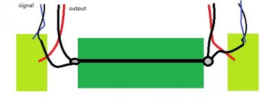
The correct grounding must look like this (also for 2 channel amp´s)
The GND from each amp channel must be connected together to one point
and from there to the star ground.
To fix the failure on the PSU pcb from Jims Audio, i made a small modification.

I cut the amp star ground connection on one side of the pcb,
and connect it direct to the amp GND on the other side.
Now both amp GND´s share one point and are connected to the star ground.
Result:
NO HUM

Thanks to all for the help !!!

On the PSU pcb from Jims Audio is a grounding failure!
An externally hosted image should be here but it was not working when we last tested it.
As you could see on the pcb, the amp GND´s left and right are connected direct to the central "star" ground.
That gives the ground loop, when the cinch cables are connected.
The correct grounding must look like this (also for 2 channel amp´s)
The GND from each amp channel must be connected together to one point
and from there to the star ground.
To fix the failure on the PSU pcb from Jims Audio, i made a small modification.
I cut the amp star ground connection on one side of the pcb,
An externally hosted image should be here but it was not working when we last tested it.
An externally hosted image should be here but it was not working when we last tested it.
and connect it direct to the amp GND on the other side.
An externally hosted image should be here but it was not working when we last tested it.
Now both amp GND´s share one point and are connected to the star ground.
Result:
NO HUM
Thanks to all
for the help !!!
Rails difference
Finally I could try to start the F5, waiting almost 2 years now.
When trying to stabilize one channel I had a very hard time to get similar values over R11 and R12 0.47 3W there was .1 volt difference between the two resistors.
I did check the power supply and gave an neat 26 V when nothing was attached.
How ever when I checked the rails again while setting up the F5 I discovered a difference in RAILS. There was over 1 V difference between + and - (24.3 and 25.6)
What could be the cause of this difference in RAILS? (bad rectifier?)
Seeing this difference I did not setup the other channel. First I want to have a good supply!
Nils
I had such a difference too when I did my first test. It came because I had a different resistance in the two rails (I had CLC, with different inductors). However, the F5 can be brought up to working without a problem.
Note that some power resistors have large deviations (5%).
However, the current dropping in from the top (1,2-1,6 Amp) can't go anywhere else than to minus, so if you measure a difference on R11 R12 that means that the resistances deviate. [0,1 volt at 1,5 amp is caused by a difference of 0,07 ohms . . ]. I measured differences of up to 0,07 myself. This might also be the case for a resistance in the power line causing the difference in the voltage...
When I noted the deviations myself, I ordered a second lot, I matched them, and used the various batches to match the slight differences in the MOSFETS.
albert
Could someone post a pic or explain a good way to add P3 to the Cviller v2.0 boards? R3+R4 are on quite a bit away from each other and I am not sure how to do this properly.
Could I super glue the pot to the board and then run some hookup wire to R3, R4 and ground? Is there a reason not to do it that way?
Could I super glue the pot to the board and then run some hookup wire to R3, R4 and ground? Is there a reason not to do it that way?
Could someone post a pic or explain a good way to add P3 to the Cviller v2.0 boards? R3+R4 are on quite a bit away from each other and I am not sure how to do this properly.
Could I super glue the pot to the board and then run some hookup wire to R3, R4 and ground? Is there a reason not to do it that way?
You could add P3 between the source leads of Q1+Q2. I think I read somewhere that you need a distortion analyzer to optimally adjust P3. So you don't need to add it on. I suppose you could add it, then adjust until you like the sound.
- Home
- Amplifiers
- Pass Labs
- F5 power amplifier