you can try something simple
like this : http://www.diyaudio.com/forums/pass-labs/186554-babysitter-papas-koan.html
like this : http://www.diyaudio.com/forums/pass-labs/186554-babysitter-papas-koan.html
PS the heat sink gets vey hot I would hardly believe the 2 fets can put out so much heat (the heat sink is 220mm wide 250mm high and 70mm deep with a mounting thinkness of 10mm , the weight is 5Kg)
54 C is not to baad
I would wory more about the Junction themperature of the mosfets
This can be taken quite easily with PT100 probe / thermometer at the drain pin of the mosfets, as drain is the one mechanicaly conected to the metal tab.
As far as I know 70 C (but maybe sameone more experienced would confirm this please)is the point at which reliability will became an issue.
Another way to put this is that the thermal resistance between mosfets and sink got to be as low as possible and it depends on mounting method and kind of insulators used.
So if you have bad thermal coupling the junctions of the mosfets may be to hot even if your sinks are relatively cold.
Goop and mica or much beter Kerafol 86/83 and just the litle screw with or witout big washer or clamps (The hiegher the pressure the beter the Kerafoll work) all make a big difference
Once you got the current right (Papa said sweet spot is at about 1.3 A) this is given by reading the voltagge drop across the resistors as you did, then you could sligtley trim to get the ofset to near zero and or adjust for less distortion
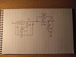
If sinks are small and you have a few spare bits (1 mosfet one ntc resistor and a pot) is easy to make a simple themperature contlolled fan to blow air on the sinks even at very low speed (the lower the speed the quiter the fan) this improve the eficency of sinks quite drasticaly.
Once you start plaiing musik the heat load on the sinks goes down as this is class A amplifier as at idle all the power get transformed in heat, as output voltagge get up same of this power get dispersed by the speakers.
litle mosfets do disperse loads of heat and is just V (rail voltagge) X A (biass current) at zero V out all of it turns in to heat
If you have litle one running around 54 C is to much
Skin is not as thik as we have especialy after few hours with a soldering iron.
You could do a few things about it
Reduce rail voltagges whit one more RC on the capacitors (CRCRC) less riple as well.
Reduce Bias
get bigher heat sinks
Fit a fan
The circuit was posted on MY F5 tread a while ago you dont need the LM 317 part if you use 2 12 V fans in series and the rest of the bits needed are just left over from standard F5 build.
F5 turbo I am ready for it (I think. see MY F5 tread)
PS I had ofset quite stable at less than 2 mV on mine
Attachments
Last edited:
I will have to test some forced cooling options as we have a youg kid in the house.
I implemented forced air cooling with two small 120 VAC fans running at about 70 VAC. Pretty low noise levels, and with the large Conrad heatsinks this was probably (I'll admit, now.....) overkill. If you want details, my F5 build thread is at:
http://www.diyaudio.com/forums/pass...usic-different-drummer.html?highlight=drummer
Regarding the F5 Turbo, when I read:
I just start to walk in circle and pray to see it in the coming days, my God it seems a very exciting project ! My F5 is about to be powered up for bias adjustment, I will push a few photos soon...
Its power supply is too big (850VA and 90,000uF/channel), so it needs a turbo...
I will build one, I will build one, I will build one, (shut up !)
ps - you can modify existing F5's to make one.
I just start to walk in circle and pray to see it in the coming days, my God it seems a very exciting project ! My F5 is about to be powered up for bias adjustment, I will push a few photos soon...
Its power supply is too big (850VA and 90,000uF/channel), so it needs a turbo...
I will build one, I will build one, I will build one, (shut up !)
F5's blew up!
I have previously constructed two pairs of monoblock F5's with no problem at all. The third set were working well until I left one on overnight by mistake. When I got to it the heat sink was cooler than normal and there was 15V across my speaker. The speaker survived.
When I pulled it apart the output transistors and some resistors had fried. So I fixed it up and all was well. So I thought I would leave both on 24/7 without the speakers connected. Next morning the second F5 had fried identically to the first. So fixed it too.
Only difference in builds is that this time I used some self adhesive heat sink washers. Grey looking like normal washers but very soft and squishy.
Anyone had trouble with these? I'm now using the normal grey washers and amps are OK (so far!).
Cap sizing for F5 mono
Hi Zen, thanks for your kind answer.
Looking at the available RIFA caps on the market, I found these ones:
PEH200 47.000uF 40V
PEH169 22.000uF 63V
I'd like to use four caps on each mono amp.
What's better ? 4 x 47000 PEH200 or 4 x 22.000 PEH169 ? I know the latter are considered among the best ones for a PSU.
I can't afford eight of those 22.000 on each amp. Apart from the price, the size and weight would be humongous. Any opinion ? thanks in advance. Carlo.
you already know what's stock FW variant
use same amount for one channel , and you're good
Hi Zen, thanks for your kind answer.
Looking at the available RIFA caps on the market, I found these ones:
PEH200 47.000uF 40V
PEH169 22.000uF 63V
I'd like to use four caps on each mono amp.
What's better ? 4 x 47000 PEH200 or 4 x 22.000 PEH169 ? I know the latter are considered among the best ones for a PSU.
I can't afford eight of those 22.000 on each amp. Apart from the price, the size and weight would be humongous. Any opinion ? thanks in advance. Carlo.
Carlo, I would go CRC with 4 caps, and I would use PEH200, as IIRC the main difference was to be 105º instead of 85º. What about 4x 47.000uF PEH169? Quite expensive though, that's why I've used PEH200 for my last amp.
Thanks Regi.
Were you able to find the 47.000 PEH169 anywhere ? I'm browsing the Internet since some days but couldn't find a source for them.
Here are the specs for the two caps:
---------uF------V----Temp---diameter-----height---ESR@100Hz---ESR@100KHz
PEH200-47.000--40------85------50mm------95mm------8---------------7
PEH169-22.000--63-----105------75mm-----105mm------6---------------4
As you can see, the PEH169 is a far different beast, both for size and specs, although the PEH200 series looks pretty good as well.
ciao.
these 47.000 63V PEH169 would be monsters ! One of them weighs 800g, while the same capacitance on the PEH200 40V series is "only" 245g
You could also look to the new Mundorf M-Lytic HC 2-pole or 4-pole caps
An externally hosted image should be here but it was not working when we last tested it.

You could also look to the new Mundorf M-Lytic HC 2-pole or 4-pole caps
I've seen them. They are priced like jewelry and labeled as "audiophile", something I don't like so much. Anyway, thanks a lot for your suggestion! ciao
Last edited:
That Mundorf M-Lytic HC looks exactly the same as my FT serie GW: Elektrolyt-Kondensatoren mit Gewindeanschluss - FTCap Fischer & Tausche Capacitors Group
Wonder how they optimized them for use in audio....
Wonder how they optimized them for use in audio....
That Mundorf M-Lytic HC looks exactly the same as my FT serie GW
I dont think can size is exact the same
but no doubt made by FT
looks exactly the same
Considering that F&T manufactured the first 4-pole lythics (me bought 4-paws in mid '80s), maybe not that surprising.
Fewer number of capacitor manufacturers than brands, in particular nowadays.
So guys, please give me your last sentence for an F5 mono amp.
I've narrowed my choice to:
RIFA PEH169 22.000uF 40V 105c x 4
RIFA PEH200 47.000uF 40V 85c x 4
Both of them are stud mount with very good ESR and L figures.
The latter doesn't sport the "EE.UU. made" label (China..?), while the 169 does it, at least on pictures.
Thanks a lot. Have a great diy new year (I mean for audio )
I've narrowed my choice to:
RIFA PEH169 22.000uF 40V 105c x 4
RIFA PEH200 47.000uF 40V 85c x 4
Both of them are stud mount with very good ESR and L figures.
The latter doesn't sport the "EE.UU. made" label (China..?), while the 169 does it, at least on pictures.
Thanks a lot. Have a great diy new year (I mean for audio
)
Last edited:
The latter doesn't sport the "EE.UU. made" label (China..?), while the 169 does it, at least on pictures.
one way would be to look at RIFA spec sheet, and carefully check can sizes, and watch if it matches other specs
- Home
- Amplifiers
- Pass Labs
- F5 power amplifier