The GR P-Chan JFET's seem to have Idss in the range of 2.8 to 6.4mA, and the BL's 5.7 to 12mA -- but the transconductances range from 20mS to 36mS in both cases.
You can get the F5 to "work" with other JFETs but the THD% will not be so low, the noise might be a tad higher as well.
By paralleling multiple JFETs you can attain a higher level of gm, at some risk of oscillation. (Note that the gm does not increase linearly with devices. Parallel devices will also reduce the noise.)
Some time ago NP suggested a 200 ohm trimpot from N & P Jfet sources with the wiper connectd to gnd. In parallel with the two 10 ohms resistors. I remember he posted a sketch...
Could this be a std halfwatter 1 turn trimpot?
If I recall correctly, the 10R resistor will dissipate a bit over 1/2 watt at peak output. Let's say that you find that the optimal resistance for this combo is 8 ohms. (10R in parallel with 40R) -- the 10R will dissipate 80% of the energy amd the 40R 20%.
I'd start with 12R and a 10R/200R combo in series, the combo in parallel with the 12R.
When you change the value of the JFET source resistor you change the gain of the amplifier.
You can also change the value of the resistances on the JFETs -- this will effectively change the transconductance of the output stage. See page 233 of Bob Cordell's book. Reduces transconductance droop under high currents.
All of these mods are attempt to get the last oink out of the pig, but it oinks pretty good without them.
That's what I tought...the 10R will dissipate 80% of the energy amd the 40R 20%.
This simple mod came after "The Sweet Spot" article. Two suggestions:1) adjust the 0.47 Ohm mosfet source restisor or 2) the Jfet source one with the trimpot.All of these mods are attempt to get the last oink out of the pig, but it oinks pretty good without them.
So, my F5 is almost complete, only the power connector is missing. I tried do make it "not so big" as the original idea was to make two monoblocks. Then the battle plan evolved as following. Please tell me if it makes sense.
I made a stereo built now with a 320 VA transformer. I love the sound. Soon I will have a balanced source, and I will try to use the stereo built in a balanced configuration. (Just connecting the two minus of the speakers together, and using each channel for each phase) If it sounds good balanced, I will build a second one. With a balanced source I should also have more gain than I need.
I am driving Sonus Faber Grand Piano with them.
I only hope I had more time to listen to that....after Christmas vacation.
Thanks to everybody for help,
Davide
Is what Nikon is proposing feasible? I have never used balanced, but I have a balanced output DAC. Will it work OK just connecting output grounds together and then one channel to one speaker terminal and the other channel output to the other speaker terminal?
Of course, on the input would be connected the IN+ to one channel and the IN- to the other.
Thanks
Of course, on the input would be connected the IN+ to one channel and the IN- to the other.
Thanks


Advice on F5 with 2SK1530/2SJ201
Hi,
I am planning another F5 build but with Toshiba MOSFETs. I have found the attached schematic in one of these threads. Just wanted to check if this is the right one that I am looking at? There seem to be so many discussions on this, just wasn't sure, which one.
Cheers
Hi,
I am planning another F5 build but with Toshiba MOSFETs. I have found the attached schematic in one of these threads. Just wanted to check if this is the right one that I am looking at? There seem to be so many discussions on this, just wasn't sure, which one.
Cheers
Attachments
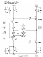
IF single ended (+/-24V rail) then R11, R12 should be 0R47.
And you should replace P1, P2 with fixed resistors after trimming.
Voltage across R3, R4 more like 3V.
Schematics not proven, so build at own risk.
Patrick
.
Should P1 and P2 behave any differently than a stock schematic to mandate replacement with fixed resistors? The reason I am asking is because that would be the case even in the case of IRFs isn't it? Or is it because of increased sensitivity of the Presets....with the combination of Toshiba Mosfets.
Thanks.
Merry Christmas to everyone!
As many of you know, the F5 power amplifier design is done and is
merely awaiting delivery of the issue of AudioXpress which was
scheduled to be mailed April 10.
I feel that it's important to support AudioXpress, a magazine with
which I have a 35 year history, and which also serves as a
mainstay for the DIY comunity. Lately they have kindly printed
projects that I had already posted on the web, but I decided that
they deserve a little better than that.
Coincidentally, I had surgery of the 10th, and having apparently
survived, I am typing this from my bed.
Do not try to lift an XA200.5.
Hi Nelson,
Nice KISS circuit similar to a MC stage I made when I was with Magnum 1979 I dig it and put it up for you to see.
Regards
Colin Wonfor
Should P1 and P2 behave any differently than a stock schematic to mandate replacement with fixed resistors? The reason I am asking is because that would be the case even in the case of IRFs isn't it? Or is it because of increased sensitivity of the Presets....with the combination of Toshiba Mosfets.
Thanks.
Merry Christmas to everyone!
Fixed resistors will exhibit less thermal drift, as their PPM temp. coefficient is smaller
Just choose the right type of resistors, some Dale RN/RL/CMF type should run just fine
nAr
yes - it will work ;
be sure to have some sort of (balanced , too ) volume control between DAC and amp

My DAC has already a volume control, so no worries
Are you saying that regarding my question? If so, why do you get less "class A power" when doing that way?Still 25w class A power but a lot more in class AB
The bridged F5will bring twice more output voltage but it will also leave class A when running at more than 2.6 Amps into the load.Are you saying that regarding my question? If so, why do you get less "class A power" when doing that way?
To get full class A power, you need more output devices, more global bias, more heatsinking, different PSU.
Two days ago I received a digital IR thermometer from Dealextreme, a cheap one. I've tested it against my body and I got 36º, so I consider it "quite" accurate despite its price.Well, then mine is sitting between 55º and 60º: I don't really know how hot is too hot, I come from the Gainclone world
After 24h of F5 on, some parts of the heatsink measure as high as 67º. I get .520v across the source resistors. Setting them to 0.600v seemed a bit high. I am considering getting it even lower for long term endurance.
- Home
- Amplifiers
- Pass Labs
- F5 power amplifier