the signal and ground is far apart from my transformer :/
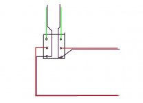
here is my simple graphical example of my wiring on the pot.
i will show up the picture later once i get a camera on my hand
here is my simple graphical example of my wiring on the pot.
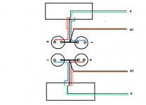
An externally hosted image should be here but it was not working when we last tested it.
i will show up the picture later once i get a camera on my hand
i think you have three problems, although one or two may be much worse than the third.
First.
The potentiometer body should have a separate wire back to the main Audio Star Ground.
Second.
The wires (green & black) from input to pot should be very close together to minimise loop area. Usually this is done by twisting.
Similarly the red and black wires from pot to amp input should be very close together, again usually twisted.
However, you have L+R+Return as a group, twisting will make crosstalk worse.
Third.
All the mains and secondary AC wiring must have a small loop area. This is to minimise the mains signal that your wiring transmits to the air. This is done by taking pairs of wires that form a flow and return circuit and twisting them together. The DC supply to the boards is +&-&Return. These three wires should be twisted as a triplet to minimise loop area.
Try First, then third, before attempting second.
I guess if I was doing something like this, I would:
- replace all signal wiring with good coax
- remove short jumper from signal ground to pot
- connect mains earth ground to chassis
- route all signal wiring well away from transformer / any primary wiring
- wire from pot shaft to earth ground if necessary
- connect circuit ground to chassis / earth ground in the manner Nelson suggest
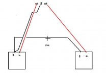
Can you do a drawing coming back the other way, from wall plug and speakers out, showing all "positives / phase" in red, "negatives / -" in black and all "ov's / earths" in green,chchyong89
it concerns me when you say
1. My F5 is running naked, there is no earth wire from my wall plug
Also you could have a dry joint in power supply caps etc,
mine dose that with my caps connected by copper wire rapped around bolts into caps, so I give them a tap to make contact and hum lessen and go's away further as I move further from speaker and crank the volume up, Its that "sweet spot"
Nelson talks about  ?
?Bobo's diagram shows minimum loop area for each pair of flow and return wires. These can be twisted to maintain and average that minimumloop area.
However, in Stereo, there is a problem. The source usually has the RCA phono output grounds connected to each other. That creates a loop in the returns and minimising the Hum Voltage around the ground loop is difficult. The loop area of the interconnect grounds and the two channels of grounding wires inside the amp must all be laid out to minimise loop area. But even this does not remove the Hum Voltage. It merely attenuates it.
However, in Stereo, there is a problem. The source usually has the RCA phono output grounds connected to each other. That creates a loop in the returns and minimising the Hum Voltage around the ground loop is difficult. The loop area of the interconnect grounds and the two channels of grounding wires inside the amp must all be laid out to minimise loop area. But even this does not remove the Hum Voltage. It merely attenuates it.
However, in Stereo, there is a problem. The source usually has the RCA phono output grounds connected to each other. That creates a loop in the returns and minimising the Hum Voltage around the ground loop is difficult. The loop area of the interconnect grounds and the two channels of grounding wires inside the amp must all be laid out to minimise loop area. But even this does not remove the Hum Voltage. It merely attenuates it.
In that case, one may disconnect one RCA ground wire.
Which one and where?
Unsolder the ground wire from one RCA input (into the amp)
with RCA1 return wire disconnected at the input, how does RCA1 circuit flow and return?
How close are the flow and return routes?
How much loop area is in that route?
Will that loop area result in greater hum at the speaker output terminals?
Will the hum be the same for both stereo channels?
If the Hum is zero for both channels, then you have done something else.
Help.
How close are the flow and return routes?
How much loop area is in that route?
Will that loop area result in greater hum at the speaker output terminals?
Will the hum be the same for both stereo channels?
If the Hum is zero for both channels, then you have done something else.
Help.
Last edited:
I do not use this trick in F5s as they are double monos.
I have built several stereo (not double mono) amps which are silent without this trick.
I had to use this trick in a 4 channels amp.
Typically: one get hum when both RCA input (from source) are connected, the hum disappear when one is disconnected
The trick works then.
Q\ with RCA1 return wire disconnected at the input, how does RCA1 circuit flow and return?
"Return" i prefer "shielding" is made
-Outside the amp : the shields are joined into the source.
-Inside the amp: the shields are joined at the star ground.
Generally, I do not connect the audio ground to chassis. It may help, i do not know.
Last edited:
Is it "hum" or "hiss" -- if the amplifier isn't connected to a low impedance source then you have the 100k plus its connecting cable sitting out there as a little antenna -- and your transformer is radiating energy.
The F5's noise is spec'd at some tens of microvolts -- if you are using the power supply setup which NP had recommended.
The F5's noise is spec'd at some tens of microvolts -- if you are using the power supply setup which NP had recommended.
There is a unique ground into the source connected to the unique amp ground. I suppose it is sufficient.alright, you shield your input.
Where does the signal flow and return if the shield does not provide the necessary return route?
Pr Leach himself tells this (scroll down to penultimate paragraph)
The Leach Amp - Part 2
I insist, i do not use this with F5.
Last edited:
If you prefer symetry:
What about the case where you have a chassis earth isolated from a signal ground. What about running those shields to the chassis earth? That way the length of the return path can be equated to the signal path for even more symmetry. I have done it that way in electrophysiological recording hardware then is extremely sensitive to input noise (30 meg input Z). I just hacked at it though not really understanding what I was doing. Seems to work.
Last edited:
Do you mean two wires + shielding, such as microphone wire?
The two wires used as signal and return, the shielding connected to earth only?
Interesting!
Though, it works only if ground and earth are not connected into the source.
Anyway, as Jackinnj said, the F5 is not concerned; it is easy to get it silent and it does not need special care for grounding. Only respect of the common rule.
Do you mean two wires + shielding, such as microphone wire?
The two wires used as signal and return, the shielding connected to earth only?
Interesting!
Though, it works only if ground and earth are not connected into the source.
Anyway, as Jackinnj said, the F5 is not concerned; it is easy to get it silent and it does not need special care for grounding. Only respect of the common rule.
Yes, that is what I meant. Two conductor with a shield, a signal conductor, a return conductor, and a shield to earth. I have wrestled with this kind of thing for years in recording equipment. Then there is a driven ground and my head starts to swim. What works one day does not work the next day. I have never waded through an academic understanding. I do know that inadvertent pathways between signal ground and chassis earth generally spell trouble for low noise high Z amplification. At least, this is true in my hands.
- Home
- Amplifiers
- Pass Labs
- F5 power amplifier