Please help me!!!!!!
I justed finished my first diy amplifier f5! But the one channel has a problem, across the R12 (0.47ohm) I have 23mv with the 5k pot to zero and the other R11 gives 0V(0.47ohm) with the 5k pot to zero, so when I try to raise the pot of R11 the voltage across R12 also rise, in addition the 100ohm resistors R6-R5-R7-R8 get quickly very very hot....
Now trying to setup only the one channel!
Thanks
Please help me!!!!!!
I justed finished my first diy amplifier f5! But the one channel has a problem, across the R12 (0.47ohm) I have 23mv with the 5k pot to zero and the other R11 gives 0V(0.47ohm) with the 5k pot to zero, so when I try to raise the pot of R11 the voltage across R12 also rise, in addition the 100ohm resistors R6-R5-R7-R8 get quickly very very hot....
Now trying to setup only the one channel!
Thanks
Its a bourns 3296 multiturn. The truth is that before powering the amplifier, I turn all the trimpots to zero by turning them anticlockwise (following the procedure written by NP), but when I fired the amplifier across the R11&R12 I had aboyt 1.2v!!!, As a new one in diy it passed a little time to realize what happened so I closed the amplifier quickly when I realised that the R11&R12 are burning with a little smoke!!! After that I turned all the trimpots full clockwise, and I fired up again, as I told you the one channel measures ok along R11 & R12 (when I get 0.50mv the output gives 0.37mv) I left it for 30minutes (only the one channel) and I didn't get any different voltages, not even the amplifier heatsinks get hot at all, is this ok!!!
What else I have to check or measure so as to help me?
(by firing the problematic channel the 100ohm resistors get really hot....)
Last edited:
As I said the R11&R12 burnt for a while (but they measure ok)! The trimpots are working ok I beleive, becase they are changing the volts across R11&R12 with the big difference R12=0.20v and R11=0v when I setup R12=0.59v then R11=0.15v!
I am afraid the problem is at Q1 &Q2 (2sk170-2sj74), in addition as I said the four 100ohm feedback resistors, when I firing the amplifier, in a second gets really hot....
I am afraid the problem is at Q1 &Q2 (2sk170-2sj74), in addition as I said the four 100ohm feedback resistors, when I firing the amplifier, in a second gets really hot....
Last edited:
Hi,
if the variable resistors are set to minimum then their resistance should be zero ohms.
This will ensure that Vgs of upper and lower output FETs is set to zero. That in turn ensures there is zero output current.
If all these zeros don't happen then the variable resistor is not doing it's job.
if the variable resistors are set to minimum then their resistance should be zero ohms.
This will ensure that Vgs of upper and lower output FETs is set to zero. That in turn ensures there is zero output current.
If all these zeros don't happen then the variable resistor is not doing it's job.
How can I check a variable resistor that it is in zero ohms, there are three legs! full clockwise or anticlockwise?
An externally hosted image should be here but it was not working when we last tested it.
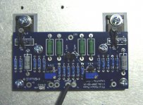
This is my layout, so connecting the polymeter to the legs 1-2 (together) and the 3 pin I must get zero ohm correct?

Last edited:
This is my layout:
An externally hosted image should be here but it was not working when we last tested it.
it will be close to zero ohms.
to check the pots are still working measure Ohms from the two legs joined to the leg by itself.. if the pot is melted replace it.
are you aware you need to adjust both pots to get the correct bias and dc offset?
for example if you wind both pots up a turn at a time you may get (example) 0.4 V and 100mV dc offset you then need to increase the othe pot which brings down the dc offset and then re measure the bias which will have probably dropped. then increase the other pot and repeat until you get the correct bias on both resistors and also a low dc offset.
how i did it was:
1 turn on P1, one turn on P2 (bias increases) say approx 0.05 V
1 turn on P1, one turn on P2 (bias increases) say approx 0.15 V
1 turn on P1, one turn on P2 (bias increases) say approx 0.25 V
1 turn on P1, one turn on P2 (bias increases) say approx 0.35 V
1 turn on P1, one turn on P2 (bias increases) say approx 0.45 V
1 turn on P1, one turn on P2 (bias increases) say approx 0.55 V
Wait about ten mins for temp to stabilize
Add a small amount to P1 , add a small amount to P2 increase or decrease P1 and P2 slightly to achieve <10mV DC offset and 0.59 or 0.6V across R11 and R12
Does that make sense to you ?
what i am trying to get across is you will need to increase the resistance on both pots slowly until you reach the correct bias level and then adjust P1 and P2 either up or down to get the correct values.
the amp is quite stable and predictable when biasing.
-Dan
Thanks for your instructions, I almost did the same thing!
But as I said I made the mistake to fire up the amplifier (for a minute) with the pot not in zero but in full resistance (my mistake).
so now the problem is:
the working channel : when I get 0.59v(stable) along R11-R12 the output gives 0.35v (stable) is there also a problem? (i left this channnel for 30 minutes but there isn't any changes in dc, also the thermistor are not very closed to mofsets body, only very closed to mofset legs)
the problematic :as I said R12=0.20v and R11=0v when I setup R12=0.59v then R11=0.15v (I didn't count the output dc offset) when I put R11= 0.45v then R12=1.2v.... In addition the feedback resistor get really hot in a second!!!
The first thing I am going to do is to check the trimpots
What else I have to pay attention or measure?
when you are adjusting the bias you need to adjust one at a time to balance the bias on the resistors aswell.
when i was biasing mine i went turn for turn on the pots and the Volts across R11 and R12 was within 0.1 V the whole way.
after you get the bias on both resistors to be the same then check the DC offset. they should not be far apart though.
any how try this before you start desoldering things i think it still may be an adjustment to get it right.
-Dan
don't set full bias on one resistor and then check the other. Bring both up slowly.
I actually never measure the bias on both resistors. I keep the meter connected across only one resistor (R11 or R12) and another meter plugged into the output. Fiddling with the pots back and forth still increases the overall bias (even if I'm adjusting the 'half' that the measured voltage is not part of). This way I might end up with slightly unequal bias across the two halves due to device non-matching but the offset is very stable.
I use the offset to set the amp. Keeping the offset within a 100mV range and adjusting back and forth. As the bias for the -ve channel goes up, offset moves negative. Once it reaches -100mV, I go and bring up the +ve bias and the offset also goes toward +100mV. Once I hit 450mV bias, I narrow the offset range to +/-10mV and do the final adjustment. Usually takes about five minutes to get stable offset and bias this way.
As I said in the working channel I have stable bias in both resistors 0.59v (though It' correct biased), but the dc offset is stable at 0.37v(too much) not even 0.05v!
The channel that has problem there is no way to make stable the bias between the two resistors! In addition when the pots are to zero position the bias to the one resistor is 0.25v and zero to the other!
If the pots are to zero ohn then the bias to the resistor should be also zero ohm?
The channel that has problem there is no way to make stable the bias between the two resistors! In addition when the pots are to zero position the bias to the one resistor is 0.25v and zero to the other!
If the pots are to zero ohn then the bias to the resistor should be also zero ohm?
this tells you that the 0r47 resistors are a different value.As I said in the working channel I have stable bias in both resistors 0.59v (though It' correct biased), but the dc offset is stable at 0.37v(too much) not even 0.05v!
You could have selected them for better matching.
Now ignore one of the Vrs and instead monitor the output offset and the other Vrs. Get the offset down to spec value.
Hi,The channel that has problem there is no way to make stable the bias between the two resistors! In addition when the pots are to zero position the bias to the one resistor is 0.25v and zero to the other!
set both the variable resistors to zero ohm. Measure them using resistance range.
Power up.
Measure the voltage across the variable resistors. It should be zero volts.
Hi,
set both the variable resistors to zero ohm. Measure them using resistance range.
Power up.
Measure the voltage across the variable resistors. It should be zero volts.
I use 2% resistors
")
Mayde when I burnt them they lost their value?
- Home
- Amplifiers
- Pass Labs
- F5 power amplifier