Hey Snokker,
I did not realize that too much capacitance could result in buzzing. I just thought it creates start-up issues.
Thanks,
Steve
Hi Steve,
The capacitance you add at the secundairy side of the transformer causes a reactant current, 90 degrees ahead of the voltage. As the transformer itself is mostly inductive it interacts with this current.
Be aware of a cos phi > 1 (I think you use pf, powerfactor) at the primary side of the transformer. This means that the capacitive reactance is bigger then the inductive; Too much elco's on a too small transformer.
This can cause instability (underdamping) on the mains. This is often the cause of buzzing transformers.
For more info check "electrical reactance" on wikipedia!
Have fun!
for 240Vac soft start I put ~50r in the primary circuit and timer bypass it at ~300ms.
For the slow charge I would prefer to use a Thermistor. It reduces the initial current when the voltage difference is high and the Thermistor is cold. As the voltage difference reduces, due to charging the capacitors, the thermistor has partially heated and allows more current to pass than if it were cold. Finally as the ClassA amp draws bias and the caps are almost charged the Thermistor should be quite warm and the resistance value low enough to simply relay bypass.
The heating Thermistor and the reducing charging voltage will give an approximation to constant current charging.
I would guess that somewhere between 1 and 10seconds would be appropriate. Test it and tell us how it performs.
A couple of sensor resistors placed appropriately and a two channel sound card to produce a couple of graphs would be very illuminating.
Right, absolutely necessary.
I'd suggest 50watt wirewound ceramic resistors at minimum.
You can get away with less, but in the event something goes wrong or delays your relay you will smoke smaller resistors.
A value around 8-10 ohms is likely to be good.
With the lower voltages maybe a higher value will suffice...
I would only put this before the transformer at the primary.
Also, do NOT use a single relay contact. Use multiple high current contacts, imo. If you just have to use a medium size "cube" relay, at least get one with 4 contacts...
My Symphony No.1 amp has 500,000ufd @65vdc rail voltage. That and >2KVa of iron... so I use very large P&B relays. You can see a pic on my website if you hunt down in the amplifier section a bit...
As I said you can figure out the time thing after you put the supply together and have it running... just look at the pulse when you bypass it... that and the time it takes for the rails to come up. On my amp I used 10 seconds... more than sufficient to bring up the rails and let the amp stabilize (no speaker relays, so don't want thumps)
I'm thinking that a soft recovery type rectifier will be best in consideration of the current waveform that will be charging the cap banks...
How many caps to achieve this total capacitance??
_-_-bear
Hey Bear,
1. That's a very nice looking amp on your site.
2. I was wondering if I would have to use relays on the speaker outputs if I use a long delay on the soft start. I was going to see if there was any appreciable dc on the outputs during the start-up. If there was, I was going to use relays. Hopefully there won't be so that I do not have to use muting relays.
3. My amp is going to be dual-mono. Each of the power supplies has a 600VA transformer - followed by a soft recovery rectifiers - followed by the caps and chokes. I have 4 caps in each power supply. Each cap is 68,000uF.
Thanks,
Steve
for 240Vac soft start I put ~50r in the primary circuit and timer bypass it at ~300ms.
For the slow charge I would prefer to use a Thermistor. It reduces the initial current when the voltage difference is high and the Thermistor is cold. As the voltage difference reduces, due to charging the capacitors, the thermistor has partially heated and allows more current to pass than if it were cold. Finally as the ClassA amp draws bias and the caps are almost charged the Thermistor should be quite warm and the resistance value low enough to simply relay bypass.
The heating Thermistor and the reducing charging voltage will give an approximation to constant current charging.
I would guess that somewhere between 1 and 10seconds would be appropriate. Test it and tell us how it performs.
A couple of sensor resistors placed appropriately and a two channel sound card to produce a couple of graphs would be very illuminating.
Hey Andrew,
I too use 240V mains for my amps. I ran a 240volt line just for the amps. The rest of my components are on a 120V line.
So just to be clear Andrew, you would place the thermistors on the secondaries of the transformers and not on the voltage rails just after the rectifiers?
I would love to give you some graphs of the results. But I do not follow exactly how to set up the test. If you could be more specific, I would love to accomodate when I complete the project.
Thanks,
Steve
Can anyone comment on the sonic pluses of using 240V vs 120V input to xfmr.
In the USA the 240vac line is going to be "stiffer" all other factors being equal.
Also the residual c**p (noise + glitchies) will tend to be common mode (on both legs) so the result is that they will often be canceled in the primary of the transformer.
[For the non N.A. readers, in the USA 240vac is 120-0-120, not 240-0]
_-_-bear
PS. in the USA you need 4 wires to meet code. 120, 0, 120 and SAFETY GROUND!
Can anyone comment on the sonic pluses of using 240V vs 120V input to xfmr.
This guy knows ... 2.47 in and you will have your answer ...
YouTube - Greek Audiophile
In the USA the 240vac line is going to be "stiffer" all other factors being equal.
Also the residual c**p (noise + glitchies) will tend to be common mode (on both legs) so the result is that they will often be canceled in the primary of the transformer.
[For the non N.A. readers, in the USA 240vac is 120-0-120, not 240-0]
_-_-bear
PS. in the USA you need 4 wires to meet code. 120, 0, 120 and SAFETY GROUND!
2 phase or 3 ?
Can anyone comment on the sonic pluses of using 240V vs 120V input to xfmr.
Hey Ichiban,
I don't know if there are any sonic benefits of not. I did it because I had some sub amps on the line and by doubling the voltage on the mains, you half the amperage. I figured that the lower the amperage the less negative inductive, etc effects there will be on the line before the transformer.
Again, I don't know if it's worth doing. But when I did it, I had relatively inefficient subs that required current. I don't have those anymore. But, I already have the 240V line in place.
Steve
1. is there any difference sound quality if i change ztx550 to bc560 and ztx450 to bc550.
if you want PM me and I will send you ztx450/ztx550.. i have a few extras
mr. pass generosity is rubbing off on me
-joe
Thanks all.
Uhm, don't want to be an *** but I just scrolled trough the last couple of pages. To an unexpecting or in experienced reader this might lead to the conclusion that it is possible to connect (or wire up) a 120v primary designed trannie to a 220v primary AC line or vica versa and expect possible sonic benefits.
As far as I know this is not the case and will most likely result in total destruction of the amp and quite likely the attached speakers as well. I would not do that.
regards,
Joris
ps I just reread the last three pages and still want to make this post. please excuse me if unneeded.
Darn, looking back i might be suggesting this would be the case for Ichiban. that was not intended
Last edited:
To an unexpecting or in experienced reader this might lead to the conclusion that it is possible to connect (or wire up) a 120v primary designed trannie to a 220v primary AC line or vica versa and expect possible sonic benefits.
As far as I know this is not the case and will most likely result in total destruction of the amp and quite likely the attached speakers as well. I would not do that.
regards,
Joris
Would the Antek tranny be ok to connect to 220~240vac line?
An externally hosted image should be here but it was not working when we last tested it.
400VA TransformerThe 400VA toroidal transformers are commonly used in the noise sensitive equipment, high-end audio products, stepper motor supply, or servo motor supply. They are specially designed to work on all standard 115V or 230V at 50Hz or 60Hz.

Its a matter of the trafo having double primary, to connect either in paralel, or series
How to is clearly shown in F5 manual
Personally, having 230V mains, I will prefer trafo with single 230V primary
But most trafos fore 115V mains seem to have double primary
Dutch Amplimo sell both options
How to is clearly shown in F5 manual
Personally, having 230V mains, I will prefer trafo with single 230V primary
But most trafos fore 115V mains seem to have double primary
Dutch Amplimo sell both options
Hi All,
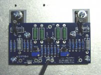
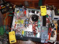
Recently I had a Le Monstre amp for sale.. it sold but the frieght was too expensive to send overseas >20kgs. so i decided to try the F5 modules i purchased from Cviller in the case... adjusted the supply to +/- 20V biased the amps...
I have to say the cviller boards are really well made. and the amp was easy to set up nice and stable....
Anyhow I have been listening to it for a couple of hours so far it is a really nice sounding amp credit to Mr Pass with this one !!!
couple of pics attached
-Dan
Attachments
- Home
- Amplifiers
- Pass Labs
- F5 power amplifier