Nelson has a very nice and simple circuit for controlling a fan. It uses a most and the idea is that the fan gets a shot of current to get it running but then runs at ow rpm afterwards. I think the issue was that while you get the fans running slow enough to be quiet,they won't start .
I'll see if I can find it.....
Fran
I'll see if I can find it.....
Fran
My laptop sounds nice to me.It sounds not as quality as but warmer than my emu1212m card.I will try jensen.What should input and output impedance be ?I think you would need a high quality transformer like Jensen. However, I don't imagine your laptop will output good quality sound. I would try an external DAC instead.
Fans are problematic. At least have the fan operation controlled by a thermistor for speed control or worst case a thermal switch or two with either resistor or control of the set pin of a 3 pin vreg so that it is quiet until it gets hot...
You're not kidding -- fans used to be a primary cause of power supply failure for telcos -- at least according to the guys who sold heat sinks!
The fan on our built in fridge just got replaced -- of course prior to this the micro-controller board was fried by a power transient, this caused the alternator board to fail as the thermal protection didn't kick in (yes, Kitchen-Aid uses a 3-phase fan, and they derive this with an SMPS) -- the failures all relate to the fan bushing which suffers premature wear. They also run these high efficiency appliance compressor fans "hot" which means shortening MTBF.
Go figure -- I run an Audio Research D-115, with a bunch of 6550's most of the time to keep the living room warm, and 4 F5's here in the lab to keep it warm and good-sounding.
heres that circuit - I used it to run 2 x 3" fans on the case of my mini-aleph (which I had biased the hell out of!).
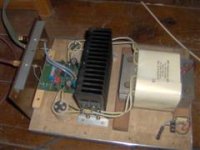
It works.... but I've missed all this part about using what looks like cpu heatsinks. I would imagine for the few dollars you'd save, you'd be better served by a big chunk o' heatsink......
Fran
It works.... but I've missed all this part about using what looks like cpu heatsinks. I would imagine for the few dollars you'd save, you'd be better served by a big chunk o' heatsink......
Fran
Attachments
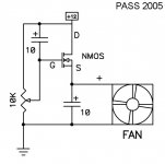
heres that circuit - I used it to run 2 x 3" fans on the case of my mini-aleph (which I had biased the hell out of!).
It works.... but I've missed all this part about using what looks like cpu heatsinks. I would imagine for the few dollars you'd save, you'd be better served by a big chunk o' heatsink......
Fran
what controls the fan on/off via temps ....
No, the fan runs continuously..... but you can adjust it to low enough speeds with this circuit and it will always start. Given that the F5 produces a fairly constant amount of heat, you are going to need it running all the time anyway with undersized/forced air heatsinks.
Fran
Fran
umut1001
There have been a member having trouble with connecting F5 to CD player having trafo output
Dont know if it was due to induction or whatever
I dont think i was ever stated whether it was due to the line trafo
But he did have another CD with ordinary output, and had no problem with that one
There have been a member having trouble with connecting F5 to CD player having trafo output
Dont know if it was due to induction or whatever
I dont think i was ever stated whether it was due to the line trafo
But he did have another CD with ordinary output, and had no problem with that one
what controls the fan on/off via temps ....
You'd have to modify the circuit.
Suggest you build one up and see what the parts and values do...
The pot obviously controls the "run" speed. So, if you had something that either modified that value, or replaced that function but was controlled by a temperature dependent device, that would do the trick. You still might want something to set minimum or maximum values... a fun project to mess about with!

_-_-bear
I used the B-E junction of a heatsink-mountable transistor to sense temperature. This was then inserted in the base of another transistor, which would turn switch the fan (fan was load for this transistor, no relay was used). The location would depend on transistor polarity - the B-E junction resistance drops as temperature increases.
A BD139 or two, a few resistors and one trimpot will net you a temperature-controlled fan")
Two fans in series across a 12V supply is enough to keep most anything cool, and will be a reasonable load for a BD139/140 without needing a heatsink.
A BD139 or two, a few resistors and one trimpot will net you a temperature-controlled fan
Two fans in series across a 12V supply is enough to keep most anything cool, and will be a reasonable load for a BD139/140 without needing a heatsink.
along the lines of something like this
If you place an 8" long pipe around the heatsink, air flow along the ribs will go from close to zero speed to 1m/s.
(for 20C ambient and 50C heatsink temperature)
1m/s air speed will drop the thermal resistance of your starcruiser heatsink by approximately 30%.
There's no need to use fans on chicken amps, i'd save forced convection for dissipation levels which natural flow can not handle.
For an example of chimney amps, see Johnny MJL21193's Class AB power amp with an MDF chassis.
For graphs : http://arxiv.org/ftp/arxiv/papers/0801/0801.0865.pdf
Or Goggle search: Stack effect formula
Attachments
Interesting Jacco... of course the flow would reach some sort of stasis at some elevated temperature, because the flow rate is related to temperature differential, so as it cools it slows the flow... stasis occurs somewhere.
cute idea!
The only downside is that the stack needs to be somewhat taller than the heat source... tests are in order!!
Got a link to that other person's amp that uses this idea?
_-_-bear
cute idea!
The only downside is that the stack needs to be somewhat taller than the heat source... tests are in order!!
Got a link to that other person's amp that uses this idea?
_-_-bear
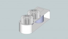
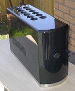
Not exactly the same, but close
Its not obvious, but heatsink goes right through the bottom plate
And heatsink top is positioned right below top plate vent holes
ALL air goes in or out at heatsink ends
It appears to be very effective, and only gets noticebly hotter when loaded into 2ohm, or less
Actually I think its more effective than outside mounted heatsink, but please note that this amp is classAB
One way to make it even more effective would be to let the heatsink top go through topplate as well
Its all about controlling airflow, and avoid chaotic air turbulence inside box
Attachments
that other person's amp
www.diyaudio.com/forums/solid-state/119958-1000-watt-sub-amp-design-build-4.html#post1469312
www.diyaudio.com/forums/solid-state/96192-post-your-solid-state-pics-here-36.html#post1519430
John's amp has fans, 2 of which are normally off, the 3d is required as the air goes also in from the sides and the Zorro air flow path.

Without the V12 headers, the permanent fan would have been a much larger model, John is as creative as his rude and crude ability.
About the effectiveness of the chimney design : www.diyaudio.com/forums/solid-state/119958-1000-watt-sub-amp-design-build-33.html#post1869087
Attachments
Last edited:
If you place an 8" long pipe around the heatsink, air flow along the ribs will go from close to zero speed to 1m/s.
(for 20C ambient and 50C heatsink temperature)
1m/s air speed will drop the thermal resistance of your starcruiser heatsink by approximately 30%.
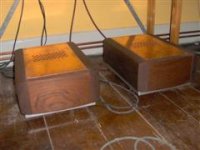
Like this? I plan to have air flow from the bottom in the form of a grated bottom for max flow... sides would be sealed. So, the convection would be enhanced by the tubes... pulling ambient air from beneath, inside the enclosure, and then out? Hummm... kinda gettin uglier by the minute... almost as bad as a "big chunk of aluminum". lol
Wait... could I cook on top of the stack... maybe a boot warmer.
eddie
Attachments

Last edited:
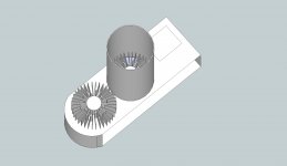
If you can find or machine something like these...http://www.cobracountry.com/cav/CAV-GT40-01-engine.jpg
It should be sized to sit on top of the first "tuning fork T" of the heatsink looking from the middle. It looks nicer if we can see the sides of the heatsinks.
It should be sized to sit on top of the first "tuning fork T" of the heatsink looking from the middle. It looks nicer if we can see the sides of the heatsinks.
Last edited:
- Home
- Amplifiers
- Pass Labs
- F5 power amplifier