I have Cmultipliers on the rails now
Interesting!
Could you tell some more about this?
Did you compare with and without?
This is pretty subjective thing, and my doubtful hearing, etc, but ...
With the standard setup, the amp is a "rather good" (!) unit - (R-C-R-C of the 33,000uF Siemens caps, the 0.1R resistors and BYV29 diodes) - with the IRFP fets and 220uF Nichicon caps for the basic Cmxs, it seems to add a bit extra detail and the "grunt" in the bass is effortless - better control all over- rails are down to about 23 volts, and apart from a bit more offset adjustment and power consumption, there doesn't seems to be other downsides - and, so far, no magic smoke either!
It also has a rather good EI transformer, instead of Torroid.
Later on, will maybe try a "beefed up" Salas shunt Reg instead of the Cmx.
Have just received some Toshiba power fets (thanks Marc) - will change these over soon and expect "more definition" in the sound again.
Hope this helps.

Hi Aleks, greetings an' all that!
Yeah, on first glance it seems a bit ridiculous but as this amp is relatively efficient ......
The simple, basic Cmx requires an extra 5 volts of raw rail supply voltage but no extra current - works well - no real problem - well worth the effort.
If keeping amp within bias of approx 1.6 amps and adding extra 0.5A for the shunt arm of the reg makes total current of approx 2.1A and as the CCS will drop about 5 - 6 volts with IRFP fets, we're looking at each rail of about +/-30 volts @ 2.1A or roughly 120VA per channel, total consumption.
It's quite a big increase in power consumption, (approx 80VA -> 120+) but still "reasonable" for an amp of this quality, especially if there is a 2 x 24v sec trannie sitting around looking for something to do - heatsinks with about < 0.25*C/W are more difficult to find, but some quiet fans available nowadays!
The improvement in low power ccts using shunt regs is quite dramatic - unfortunately, and there's bound to be other problems apart from the extra heat, but it's very attractive, no and worth a good look?
Hello,
Here I attached a photo of my F5 square wave picture @ 20kHz (approx.10R dumb load) and the original square wave @20kHz directly from generator to scope. Also for compare here is Leach amp square wave picture@ 20kHz. What causes these peaks F5 picture?
Is it a generator failure which is old maybe? Or, f5 does not work as is necessary>? Sound of my F5 is great IMHO.
Thanks in advice.
Osscar ,
Is the leach the last pic ? F5 first 2 ?
I think Nelson used 1 W @200 kHz -- this one will round off slightly because there are some silver mica's on the input.
An externally hosted image should be here but it was not working when we last tested it.
Here's a different generator -- the PG501 --
An externally hosted image should be here but it was not working when we last tested it.
...With the standard setup, the amp is a "rather good" (!) unit - (R-C-R-C of the 33,000uF Siemens caps, the 0.1R resistors and BYV29 diodes) - with the IRFP fets and 220uF Nichicon caps for the basic Cmxs, it seems to add a bit extra detail these over soon and expect "more definition" in the sound again...
Is the Cmx used standalone or added to the R-C-R-C?
f5 bias
I successfully biased my newbuilt f5, both channels at 0.59 VDC after 2 hours of warm up.
DC offset in the output of one channel is 90mV and the other is 0.25V. This is way out of NP's recommended value, especially the second value. Is it safe to hook the amp to the speakers at this condition? Any recommendation as to what can be done to bring the offset down to at least 50mv (NP's least acceptable value).
Thanks for any help as I'm really anxious to listen to the amp (like right now!!!)
pedrop
The way I understand it is that each pot controls the relative drive of the half to which it is connected, so increasing the positive side pot increases the offset above zero, and the reverse for the one on the negative side (makes offset negative).
You'll have to readjust the bias. As per the pdf, you have to alternate adjusting the pots. I basically monitor the output with one DMM, and the voltage across one resistor with another. Then keep increasing the bias starting at zero. Once I get about 50mV offset in one direction, then adjust the next pot, and back once the offset swings to the opposite polarity 50mV.
Once I reach around 450mV bias I alternate every 25mV instead of 50mV, and once it hits 570mV, I use a finer adjustment. I strive for as low an offset as possible, not necessarily the matching of the voltage across R11 and R12, there will be small differences due to non-matching of the output devices, I think.
I ended up with 300mV offset the first couple of times before I figured out this method. It is pretty obvious to those who've built discrete amps before, but this was my first and it took me some time to understand the adjustment procedure fully.
Short the input when making the adjustment. I have 0mV on one channel (less than 1mV) and -3.5mV on the other, the second also has a bit of less bias so it needs a little more on the positive side, I'll be doing that a bit later, but 1mV is achievable with some patience.
I watched it every 30 seconds for 10 minutes -- started at 32mV, 53mV then worked it's way down to 26mV, oscillating back and forth about a trend. I ran it at 5W into an 8 ohm load.Has anyone monitored the offset during warming up?
Starting from cold.
Hello,
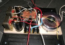
After following this thread for a while I've started building my F5.
The power supply is finally done, it always takes more time than you think to build something")
Specs CLC PS: 500VA - 2x (MUR3020 - 47000uf - 10mH - 2x22000uF)
Next: softstart and drilling holes in the heatsinks.
regards,
Danny
After following this thread for a while I've started building my F5.
The power supply is finally done, it always takes more time than you think to build something
Specs CLC PS: 500VA - 2x (MUR3020 - 47000uf - 10mH - 2x22000uF)
Next: softstart and drilling holes in the heatsinks.
regards,
Danny
Attachments
Hi Danny,Hello,
After following this thread for a while I've started building my F5.
The power supply is finally done, it always takes more time than you think to build something
Specs CLC PS: 500VA - 2x (MUR3020 - 47000uf - 10mH - 2x22000uF)
Next: softstart and drilling holes in the heatsinks.
regards,
Danny
thanx to share your work&experience with us - "behind steppers"...
Hope to here from you very soon about bias setting & sound.
Cheers,
- Home
- Amplifiers
- Pass Labs
- F5 power amplifier