the current limit is set too low for 8ohm speakers played loud.I like the sound of the F5 without current limiter more, may be because my Thiel SCS 4 has only 4 Ohm.
But my current is going up and up, slowly but sure. Will be there a stop? Or is it impossible to get a balance?
Oh I forgot I put away the thermistors too!
It is far too low for 4ohm speakers played loud.
If your amp blows up, or takes out your speakers, because you deleted the thermistors, then you deserve all you get.
If your amp blows up, or takes out your speakers, because you deleted the thermistors, then you deserve all you get.
A bit harsh I would say

Anyway, with multiple output devices I suppose theres no need to worry
Anyone know if the Large gold heat sinks over on the Apex thread in vendors forum would work for F-5?
Yes they will. Use 2 per channel.
Attachments
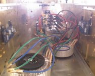
Chokes mounting in CLC power supply
I am using some Hammond 159ZL chokes for the CLC power supply. With air core inductors I have read that the inductors should be mounted as far away from each other as possible (and/or at 90deg angles to each other) to minimize magnetic coupling.
When using the iron core Hammond chokes, is mounting proximity still an issue? Or, is it not that significant since more of the magnetic field will be concentrated atthe iron core?
Thanks,
Steve
Yes they will. Use 2 per channel.
They are 170x250mm
Yes, 2 pr channel ought to work
I would prefer more like 4 pr channel
But will it still be a bargain?
Last edited:
the current limit is set too low for 8ohm speakers played loud.
It is far too low for 4ohm speakers played loud.
If your amp blows up, or takes out your speakers, because you deleted the thermistors, then you deserve all you get.
I trust in God and Nelson Pass:
The circuit of Figure 5 illustrates the basics and does in fact work, but has a tendency toward instability ...and the bias drifts with temperature, requiring a lengthy adjustment period.
.... This allows adjustment of the output stage bias current and also the output DC offset.
We can stop here, and the amplifier will be fully functional. The remaining additions will enhance temperature tracking and provide for output current limiting.
if the heatsinking is marginal or the ambient temperature rises then the thermistors are no longer optional.has a tendency toward instability ...and the bias drifts with temperature,
If the heatsinking is designed for worst case condition as Pass would do, then the stability with temperature brought about by adopting the full thermistor compensated circuit is neither a problem nor a necessity , just a time saving exercise.
Fore every bit I learn here it seems wise to repeatedly return to Nelsons F5 manual, and read again, and again
Every time I understand a bit more, bit by bit
Thanks
Could seem wise to mount the thermistors, like Andrew suggests, even if leaving out Q5/Q6
R11 and R12 are fore thermal stability it seems
When doing the multiple outputs thing, slightly bigger R11/R12 might improve thermal stabilty, right
Nelson did mention this, some time ago
if the heatsinking is marginal or the ambient temperature rises then the thermistors are no longer optional.
If the heatsinking is designed for worst case condition as Pass would do, then the stability with temperature brought about by adopting the full thermistor compensated circuit is neither a problem nor a necessity , just a time saving exercise.
Thank you Andrew! At the moment I can put my hands very long on the heatsinks (0,6 V over R12/119). The rise seems to stop now.
After having thought that laterals, like renesas wouldnt work, I thought I better read a bit, which put a small smile on
Regarding bias pots
Would someone please tell how to orient them
Original F5 schmatic shows the two bias pots mounted opposite each other
Others dont, but mount both the same way
Hi,
Set the bias pots to zero. On CVillers' board he has legs 2&3 together which means you turn completely counter clockwise to zero it. On Peter Daniel's board he has pins 1&2 together which means you start with the pot turned completely clockwise and bias it by turning it counter-clockwise.
Fore every bit I learn here it seems wise to repeatedly return to Nelsons F5 manual, and read again, and again
Every time I understand a bit more, bit by bit
Thanks
Could seem wise to mount the thermistors, like Andrew suggests, even if leaving out Q5/Q6
R11 and R12 are fore thermal stability it seems
When doing the multiple outputs thing, slightly bigger R11/R12 might improve thermal stabilty, right
Nelson did mention this, some time ago
Thank you Tinitus! When the affairs gets too hot, I`ll return to the thermistors!
No, they can't. Interpretations do.
One more time,
If you don't turn the volume knob past 8 o'clock you can use 1/16W resistors.
Hi Juma,
Thanks for the information. I don't mean to try your patience here
but you are dealing with a newb who only bought his first multimeter in march.If you could be so kind as to identify the 6 elements you used in your calculation. I see R1&R2, R5&R6, but wasn't sure if you are counting R7&R8 or Q1&Q2 or the mosfets or even R11&R12, and what about the speaker itself? Shouldn't that count too?
Any response would be appreciated.
Garrett
Me and two of my friend will make a green factory pcb of F5..i tell them that i want to put thermistors and bc 546 transistors but they dont want to use them..so they want to build the simpliest amp.because they used bc transistors and couldnt run the amp..when they put off the bc transistors it started to work.what do you think about it?
i have 50cm long 10 cm height 1.5 kilograms of aluminium heatsink..do you think its enough for one channel while not using thermistors and bc transistors?i want to use them but my friends dont
i have 50cm long 10 cm height 1.5 kilograms of aluminium heatsink..do you think its enough for one channel while not using thermistors and bc transistors?i want to use them but my friends dont

They have probably put them in the wrong way
Cvillers board is tricky using the BCs
When I work on my F5 layout I prefer to do it with original ZTX, which makes it easier to refer to F5 schematic
If I want the BCs instead, its just to reverse them
Besides, I think Cviller said he made an error on the silkscreen, reversing ebc, one side only, as I recall it
But read Cvillers manual, its all carefully explained there
Your heatsink
If 500x100mm is the base size, then 100mm height is not sufficient
But also depends on the finning height
Height usually refers to finning size
Length would usually be the height of your box
Last edited:
 (dont hear Mr.Pass )

- Home
- Amplifiers
- Pass Labs
- F5 power amplifier