Hi dave,
Sounds like a nice big project to keep you busy and warm during the winter!")
If I were you I think I would build 6 channels in three boxes - then you can use them for other purposes later.
The 45VAC doesn't sound perfect for this you need to get your rails down to ~2x23V.
Sounds like a nice big project to keep you busy and warm during the winter!
If I were you I think I would build 6 channels in three boxes - then you can use them for other purposes later.
The 45VAC doesn't sound perfect for this you need to get your rails down to ~2x23V.
I reversed channels and disconnected signal and output and the transformer still buzzed after warmup.
Ok, though it was aimed at the humming speaker. Did you check that
8-10 mv around zero (Is negative DC offset an issue?)
Nothing wrong there
I adjusted slightly to keep offset above zero.
?
I do think I have two problems: instability due to earlier mistakes and a transformer.
Maybe not. Did you check your signal wires, and ensured that they are away from supply lines. I think it has been suggested to use only shielded signal wire
You may have missed it, but it was suggested to try and decouple transformer mechanically by using rubbers. I may be enough to make the buzzing inaudible, and its cheap
Last edited:
N&P channel mismatch
Hi Mr. Pass,
This was on the J2 thread but thought I'd ask here for the sake of relevance. Were you referring to trimming R11/R12? As for the 2nd part is my sketch correct? Not that I have anything to analyze with but perhaps I'll look for something on eBay if it seems worthwhile.
Nelson Pass from Post 169 FirstWatt J2 thread:
The IR P channel parts have higher distortion. You could use
the Fairchilds, or take a look at Toshiba or Harris (if you can
find them).
The N vs P channel mismatch is a small source of distortion
down around a watt or so, which is why you want to be
able to trim the Mosfet Source resistors values a bit (if you
have the analyzer handy). Also, it is effective to use a
couple hundred ohm pot, wiper grounded, connected across
the Sources of the input JFETs and trim for least distortion at
1 watt.
Hi Mr. Pass,
This was on the J2 thread but thought I'd ask here for the sake of relevance. Were you referring to trimming R11/R12? As for the 2nd part is my sketch correct? Not that I have anything to analyze with but perhaps I'll look for something on eBay if it seems worthwhile.
Attachments
Ok, though it was aimed at the humming speaker. Did you check that? No I didin't. But good tip.
? and Nothing wrong there What I mean here is I raised the offset since, if set to zero, it would cycle between +4mv and -4mv. Raise it to 8 or 10 and it stays zero or above. As a novice, I take things literal.
Maybe not. Did you check your signal wires, and ensured that they are away from supply lines.Yes. And shielded.
RubbersDidn't have any. Used speaker dampening stuff. And loosened it. Did reduce the amplification of the buzzing but it still buzzed.
Have all the resistors in a new board. Add the rest of the parts tonight. Test tomorrow to see if I had one problem. Thanks for all your input.
Q: Is transformer buzzing alright if I can isolate it and make it inaudible?
? and Nothing wrong there What I mean here is I raised the offset since, if set to zero, it would cycle between +4mv and -4mv. Raise it to 8 or 10 and it stays zero or above. As a novice, I take things literal.
Maybe not. Did you check your signal wires, and ensured that they are away from supply lines.Yes. And shielded.
RubbersDidn't have any.
Used speaker dampening stuff. And loosened it. Did reduce the amplification of the buzzing but it still buzzed. Have all the resistors in a new board. Add the rest of the parts tonight. Test tomorrow to see if I had one problem. Thanks for all your input.
Q: Is transformer buzzing alright if I can isolate it and make it inaudible?
Ok, though it was aimed at the humming speaker. Did you check that? No I didin't. But good tip.
? and Nothing wrong there What I mean here is I raised the offset since, if set to zero, it would cycle between +4mv and -4mv. Raise it to 8 or 10 and it stays zero or above. As a novice, I take things literal.
Maybe not. Did you check your signal wires, and ensured that they are away from supply lines.Yes. And shielded.
RubbersDidn't have any.
Have all the resistors in a new board. Add the rest of the parts tonight. Test tomorrow to see if I had one problem. Thanks for all your input.
Q: Is transformer buzzing alright if I can isolate it and make it inaudible?
Scranton, My F5 trannies have a tiny buzz to them, but it's not audible through the speakers, only if your standing a foot or so away from it.
adjustments
Hi Mr. Pass,
Thanks for the reply.
Just to confirm, you are referring to R11&R12=0.47ohm 3watt source resistors, right? It does seem that it would be difficult to adjust this value.
While on this subject, on the last page of the F5 manual it says:
"If you have the equipment to see it, you may find that different gain devices will give you a small peak somewhere just below 1MHz. I have found that you can trim this by playing with the values of R13 and R14, but as both values approach 0 ohms, you are likely to see parasitic oscillations."
Is this also doing the same thing as the afore mentioned adjustments? It continues:
"You can additionally limit frequency response with an input capacitor across R10, and also in the feedback loop with capacitance across R5 and/or R8."
Approximately what value caps are we talking here? I've read this whole thread and I don't recall anyone mentioning that they did this. If anyone has, please comment. The only thing said about adjustments was Than1971 in a post about fiddling with R1 & R2 to increase/decrease 2nd/3rd harmonic.
Garrett
I meant the 3 watt resistors on the Sources of the power
Mosfets going to the supply rails.
And yes, your drawing would be correct.
Either approach works - the pot is more convenient.
Hi Mr. Pass,
Thanks for the reply.
Just to confirm, you are referring to R11&R12=0.47ohm 3watt source resistors, right? It does seem that it would be difficult to adjust this value.
While on this subject, on the last page of the F5 manual it says:
"If you have the equipment to see it, you may find that different gain devices will give you a small peak somewhere just below 1MHz. I have found that you can trim this by playing with the values of R13 and R14, but as both values approach 0 ohms, you are likely to see parasitic oscillations."
Is this also doing the same thing as the afore mentioned adjustments? It continues:
"You can additionally limit frequency response with an input capacitor across R10, and also in the feedback loop with capacitance across R5 and/or R8."
Approximately what value caps are we talking here? I've read this whole thread and I don't recall anyone mentioning that they did this. If anyone has, please comment. The only thing said about adjustments was Than1971 in a post about fiddling with R1 & R2 to increase/decrease 2nd/3rd harmonic.
Garrett
transformer hum can be worse if excessive AC non symmetric waveform are passed (=AC + DC).
This can be alleviated by fitting a DC blocking filter to the mains fed primary circuit.
my Naim amps did this quite frequently.
i placed an order for a 18+18 500VA TX from SumR. the other TX i have from Richard is dead quiet. not terribly expensive at $98 either. the PS will be in a separate chassis a la Naim for possible future Pass recipes. i've opted not to go down the bridged amp route for now - it's time i started playing around with FR drivers.
heatsinks arrived today too!
Did that price include potting?
Did that price include potting?
no. $130 total for an encapsulated/shielded, plus shipping is $26 to MN. i had Richard pot my other TX for a B22 headphone amp/preamp that some builders have had noise problems with. although the non-potted version does have a "banded shielded core" to help absorb some EMI. lead time is 1 wk or so.
no. $130 total for an encapsulated/shielded, plus shipping is $26 to MN. i had Richard pot my other TX for a B22 headphone amp/preamp that some builders have had noise problems with. although the non-potted version does have a "banded shielded core" to help absorb some EMI. lead time is 1 wk or so.
I'm still debating with myself about getting another 300VA Plitron to make mono blocks or getting 500-600VA transformer for a stereo amp. I noticed the SUMR transformers don't regulate quite the same as Plitron. Not sure if this would affect anything. Just want to be sure to get proper secondary voltages so everything is running in the sweet spot.
I'm still debating with myself about getting another 300VA Plitron to make mono blocks or getting 500-600VA transformer for a stereo amp. I noticed the SUMR transformers don't regulate quite the same as Plitron. Not sure if this would affect anything. Just want to be sure to get proper secondary voltages so everything is running in the sweet spot.
to put your mind at ease: http://ecmweb.com/mag/electric_basics_transformer_voltage_2/
build two completely separate monoblock power amplifiers.I'm still debating with myself about getting another 300VA Plitron to make mono blocks or getting 500-600VA transformer for a stereo amp.
Locate each immediately behind the speaker terminals with very short speaker cable.
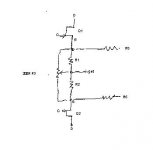
P1/r3
Thanks for the reply.
One other thing that I have been wondering about is the P1/R3 portion of the circuit (the 2.2K paralleled with the 5K trim pot). Why not just use a 1.5K trim pot and save the resistor?
Garrett
If you have a scope and/or distortion analyzer, then you
can play with this. Try different values, starting with values
close to the stock values and see what you get.
Thanks for the reply.
One other thing that I have been wondering about is the P1/R3 portion of the circuit (the 2.2K paralleled with the 5K trim pot). Why not just use a 1.5K trim pot and save the resistor?
Garrett
Thanks for the reply.
One other thing that I have been wondering about is the P1/R3 portion of the circuit (the 2.2K paralleled with the 5K trim pot). Why not just use a 1.5K trim pot and save the resistor?
Garrett
I don't know for sure, but one benefit might be to prevent mass destruction if the pot goes open for some reason.
I don't know for sure, but one benefit might be to prevent mass destruction if the pot goes open for some reason.
Yes, but also it allows you to fine tune it so you can adjust by tiny amounts to get your DC offfset to almost zero
Fran
Has anyone tried using switchmode power supplies but incorporating crc or clc at the output to remove any of the noise switch modes are renowned for?
This is something I would like to investigate but I am not sure where I can pick up a 500 Watt switchmode with the appropriate votages
This is something I would like to investigate but I am not sure where I can pick up a 500 Watt switchmode with the appropriate votages
Banned
Joined 2002
Has anyone tried using switchmode power supplies but incorporating crc or clc at the output to remove any of the noise switch modes are renowned for?
This is something I would like to investigate but I am not sure where I can pick up a 500 Watt switchmode with the appropriate votages
switchmod on a class a ? are you crazy ? way to much work way to much noise. Not worth it at all. Toroidial transformer caps etc etc
- Home
- Amplifiers
- Pass Labs
- F5 power amplifier