take a first assumption that the operating Vgs is 500mV.
That leaves ~24.1V across the Vr=3870.
Is~6.2mA.
Look up the test data or graph for the actual Vgs of the chosen jfet Idss=XYmA and read off the Vds.
Recalculate the Vr current and you are there.
For the circuit as shown I would select an Idss ~8mA
But, that high Vdg~25V worries me.
edit.
should Vvr be 24.6-(-0.5)=25.1V?
Bobo, the source is at Vgs given from 6.4 mA on R1.
Andrew, i'm simuleting the F5 front end for choose to fet the closest possible in Vgs for N and P channel, because with those I have now, choosen casually, I have one trimmer (on the J74) that is to much sensible to the regulation, whili the other is less sensible, so easy to regulate, and the bias chosen from NP in the F5 project is 6mA.
Andrew, i'm simuleting the F5 front end for choose to fet the closest possible in Vgs for N and P channel, because with those I have now, choosen casually, I have one trimmer (on the J74) that is to much sensible to the regulation, whili the other is less sensible, so easy to regulate, and the bias chosen from NP in the F5 project is 6mA.
that is to much sensible to the regulation
According to Nelson's recommendations, it is not necessary to match jfets.
I have built two amps without matching neither problem.
May be it will behave a little differently when using thermistors and biasing @1,3A.
hi to all,
I have made some mesure of the out of my new build F5.
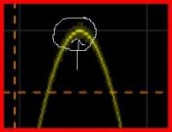
I can't obtain a square as stable as in the service manual
square wave
square wave
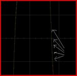
power noise ( in the capacitor filter)
may be, I have a grounding problem ? or the amplifier is too fast ? 160ns of rise time
test made with 8 ohm resistive load
or the amplifier sound great.
biased at 1.34A and 3mv of outpu offset.
Excuse-me for my poor english.
regards
lalaina
I have made some mesure of the out of my new build F5.
I can't obtain a square as stable as in the service manual
An externally hosted image should be here but it was not working when we last tested it.
square wave
An externally hosted image should be here but it was not working when we last tested it.
square wave
An externally hosted image should be here but it was not working when we last tested it.
power noise ( in the capacitor filter)
may be, I have a grounding problem ? or the amplifier is too fast ? 160ns of rise time
test made with 8 ohm resistive load
or the amplifier sound great.
biased at 1.34A and 3mv of outpu offset.
Excuse-me for my poor english.
regards
lalaina
Your top trace looks like a bit like an inductive component ringing. Output inductor ? It could be also be down to grounding, the input ground being contaminated in some way.
The middle trace is of more concern, there appears to be some oscillation occuring. Connect your scope probe tip and ground together... should be perfectly clean trace... now keeping them shorted touch the amp ground. Does the scope trace "thicken" and show that HF oscillation. If so try a low value (100 ohm say) in the scope ground lead.
Remember that absolutely nothing in audio will approach those rise times... I know that's another argument, we won't go there
looks like some oscillation which I am guessing -- but perhaps 3MHz? Just about the f3 frequency of the gate stopper and input capacitance of the MOSFET.
You can experiment with the value of the gatestopper. As the value increases the f3 is lowered, but too high a value and the amp will break into oscillation. I've used different values of gatestoppers on N and P channel devices.
On the boards which I burned for myself I have a very short run both from gate-stopper to the MOSFET, and from JFET drain to gate-stopper. I've also used everything from Ohmite TWW5, Mills, Jaro's and Dales as the 0.47R/3W resistor and haven't seen this as a source of that type of oscillation.
Can you demonstrate for us a 20kHz sine wave so we can look at the top and bottoms?
Hi Lalaina,
Is your F5 boxed now?
Could you show a picture of the wiring?
From the PDF manual:
..."A caveat is in order here – this is a very wide band amplifier with a high input impedance. In order to prevent the output voltage from bleeding back to the input at very high frequencies (thus making a i ne power oscillator), keep the input and output cables separate, and don’t externally connect the speaker ground to the input ground. Good ground shielding on the
input cables is important, and caution is called for in using Litz and other specially low inductance / high capacitance cables." ...
massimo said:To get the max efficiency, one should fix the two mosfet exactly at the center of each heatsink. That means about 200 mm apart and at 82 mm high
Massimo,
I have read that the heat source (mosfet) should be placed at 1/3 up from the bottom, not centered vertically. (heat rises through convection)
Horizontally, yes. But vertically no.
Ron
I'm sorry if I missed this in the 180-page thread, but are there any reliable substitutes in the Digikey catalog for the input pair J108/K170? I can't seem to find those FETs anywhere, but D-K has quite a few complementary (matched??) pair FETs in SOIC-8 packages. And they are reasonably cheap, around 3 dollars each.
I assume there's a catch there somewhere, or could I just pick one of those with the right voltage and current ratings? Or is there more to it? I'll be using perfboard and SOIC->DIP adapters to mount them.
There's another thread around here about getting the same FETs for the F4, and it turned up the k370/J74, and those are not on D-K either. I basically want to save on shipping costs, so would prefer to get everything from a single source if possible.
Thanks for the assistance
you need high transconductance, medium voltage Vds, lowish noise, jFets of both N and P channel.
Have you downloaded the PASS manual for the F5?
The Pchannel are often the ones that are difficult to source.The input JFETs used are 2SK170 or 2SK370 for the N channel parts (Q1), and 2SJ74 or 2SJ108 for the P channel parts (Q2). In these cases the Idss selection code is BL, although V and GR types will also generally work fine. The primary thing about these particular parts is the transconductance figure of 20 mS – many of the potential substitutes are much lower at 4 to 10 mS.
Have you downloaded the PASS manual for the F5?
Yup, and I can't find any of those parts, either 74/370 or 108/170 I poked around here on DIYA trying to get an answer and I dug up this thread
http://www.diyaudio.com/forums/showthread.php?threadid=101580
But it didn't help any. I'm trying to scour the D-K pages looking for alternates. The voltage ratings are easily available but getting the gm and noise figures are proving quite a task.
I poked around here on DIYA trying to get an answer and I dug up this threadhttp://www.diyaudio.com/forums/showthread.php?threadid=101580
But it didn't help any. I'm trying to scour the D-K pages looking for alternates. The voltage ratings are easily available but getting the gm and noise figures are proving quite a task.
sangram said:I'm sorry if I missed this in the 180-page thread, but are there any reliable substitutes in the Digikey catalog for the input pair J108/K170?
I've ordered from:
www.amb.org
www.ampslab.com
and have heard good things about:
www.tech-diy.com
These are all based in the US though - contact them to see if they will ship to India. Alternately, I'm sure there are places in Europe that stock these parts - the shipping may be a bit more reasonable.
-j
Thanks a lot for the responses, and even to those who emailed me
I was hoping to save on shipping cost by using a single source for all my parts. I notice that Jack has complete partlists for the F5, so maybe that's the ticket. He does mention something about customs, so I'm assuming he ships international.
European suppliers may have slightly lower shipping, but the parts seem to be more expensive.
I noticed in the 6moons review that Nelson has used 5% Panasonic Metal oxide resistors from D-K. Would there be any downside to just using resistors available locally? The quality of resistors here isn't the best - values may be off tolerance, suspect materials may be used, and resistors may be significantly inductive. But much, much cheaper.
Or potentially, an upside to using 'premium' resistors in this design?
Thanks again!
F5
hi
many thanks to all your replies , very helpfull for me.
After some test, I have changed the 3 wires ( +, - , GND) between the capacitor of the power supply and the amplifier card to a torsaded computer lan CAT6 wire.
like this (one channel only for the test)
and this is the result of the trace , more stable than before
and this
at 20khz
and for the fun at 1Mhz
my power supply , CRC 40 000µf+(0,68/4) +100 000µf for each line
I think that I use a fake 9240 (local seller) , I will post the trace on the gate of the 240 and the 9240. I think that the 2940 that I use have too much capacitance between the gate and the source. I'v forget to save it during test.
Thanks to all
Lalaina
hi
many thanks to all your replies , very helpfull for me.
After some test, I have changed the 3 wires ( +, - , GND) between the capacitor of the power supply and the amplifier card to a torsaded computer lan CAT6 wire.
like this (one channel only for the test)
An externally hosted image should be here but it was not working when we last tested it.
and this is the result of the trace , more stable than before
An externally hosted image should be here but it was not working when we last tested it.
and this
An externally hosted image should be here but it was not working when we last tested it.
at 20khz
An externally hosted image should be here but it was not working when we last tested it.
and for the fun at 1Mhz
An externally hosted image should be here but it was not working when we last tested it.
my power supply , CRC 40 000µf+(0,68/4) +100 000µf for each line
An externally hosted image should be here but it was not working when we last tested it.
I think that I use a fake 9240 (local seller) , I will post the trace on the gate of the 240 and the 9240. I think that the 2940 that I use have too much capacitance between the gate and the source. I'v forget to save it during test.
Thanks to all
Lalaina
- Home
- Amplifiers
- Pass Labs
- F5 power amplifier