stein2 said:
That's 35Amperes, 100Volts, use a small bolt and fix it to a metal (preferably Aluminium) surface, that should do the trick. The bridge itself is ok.
")
it is 35 A, 1000Vrrm, 700Vrms input bridge.
AndrewT said:Hi,
bolt that rectifier to a heatsink. Use thermal compound to help reduce thermal resistance.
ClassA amplifiers draw a continuous power that does not give the rectifier any significant rest period. It needs to be cooled.
Andrew is right, even bolt it to the chassis, the heatsink does not need to be large just reduce the thermal stress a little.
-Dan
danieljw said:
it is 35 A, 1000Vrrm, 700Vrms input bridge.
I stand corrected
I've just checked, mine are KBPC2510 and are bolted to an Aluminum surface...
samoloko said:I got buzz - ground loop issue
are there separate power ground and signal ground
at my setup everything goes to central ground at the filter caps
I don't use safety ground wire at the moment
Only the mains ground (earth?!) goes to chasis. See to gather all grounds into a single point between your PSU filtering caps, and from there, via a thermistor, connect the amps GND to the same point on chasis where you connected the mains grounding. Meaning, there should be a NTC (~10-20 ohms) between "signal" and mains grounds. It's simple and then you shouldn't have any audible noise from the amp. However, you should connect the safety ground wire to the chasis. Amps often pick up crap and amplify it, if not grounded properly
DO NOT put your main Audio Ground on the wire/trace/plate between the smoothing caps.
Instead place the main Audio Ground near the midpoint of all the points that need to be referenced to it.
Then connect the PSU Zero volts between the smoothing caps to this Audio Ground.
Also, connect the PSU Zero volts to the chassis using a disconnecting network.
Instead place the main Audio Ground near the midpoint of all the points that need to be referenced to it.
Then connect the PSU Zero volts between the smoothing caps to this Audio Ground.
Also, connect the PSU Zero volts to the chassis using a disconnecting network.
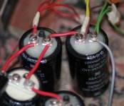
Investing into a few decent eyelets to make connections between the caps would surely help to do it much better than this... We all know you can http://www.diyaudio.com/forums/showthread.php?postid=1612093#post1612093
http://www.diyaudio.com/forums/showthread.php?postid=1612093#post1612093stein2 said:
I stand corrected
I've just checked, mine are KBPC2510 and are bolted to an Aluminum surface...
All good,
i have used a couple before i like the construction / layout of these bridges.
-Dan
AndrewT said:DO NOT put your main Audio Ground on the wire/trace/plate between the smoothing caps.
Instead place the main Audio Ground near the midpoint of all the points that need to be referenced to it.
Then connect the PSU Zero volts between the smoothing caps to this Audio Ground.
Also, connect the PSU Zero volts to the chassis using a disconnecting network.
Andrew sorry for the ignorance but what do you mean by disconnecting network ?
-Dan
danieljw said:
Andrew sorry for the ignorance but what do you mean by disconnecting network ?
-Dan
Probably meaning the same what I tried to explain. A thermistor between chasis and PSU zero volts.
2 thermistors
Stein, You could emphasize the use of a seperate thermistor for each channet PSU 0v to the GND terminal, as your photo in post 1801. There is one thing that can easily be done to improve performance - replace all those damn block bridges with good quality shottky diodes - even the humble MUR820 type devices will return big improvements in clarity, transient response, base, etc and the use of m/oxide power resistors between caps will now "not have to choke off the diode noise, etc" - another improvement. (please excuse the tortured wording - like me, also needs upgrading!) You may have seen the use a small resistor (about 0.1R)between the diodes (bridge) and the first cap (the "Ripple Cap") - it doesn't work in all circumstances and for all types of caps, but as it's a simple exercise, just try it - it normally adds extra smoothing and detail to the sound, despite the "SIM" programs saying the opposite. Another thing that's often overlooked is the use of really good wire throughout the whole amp, not just the input & output connecting wires.
Stein, You could emphasize the use of a seperate thermistor for each channet PSU 0v to the GND terminal, as your photo in post 1801. There is one thing that can easily be done to improve performance - replace all those damn block bridges with good quality shottky diodes - even the humble MUR820 type devices will return big improvements in clarity, transient response, base, etc and the use of m/oxide power resistors between caps will now "not have to choke off the diode noise, etc" - another improvement. (please excuse the tortured wording - like me, also needs upgrading!) You may have seen the use a small resistor (about 0.1R)between the diodes (bridge) and the first cap (the "Ripple Cap") - it doesn't work in all circumstances and for all types of caps, but as it's a simple exercise, just try it - it normally adds extra smoothing and detail to the sound, despite the "SIM" programs saying the opposite. Another thing that's often overlooked is the use of really good wire throughout the whole amp, not just the input & output connecting wires.
Isn't Nelson Pass saying the opposite?- replace all those damn block bridges with good quality shottky diodes -
I think you'll find that Nelson uses them because all 4 diodes are on the same substrate and hence are all matched to each other, but the diodes themselves aren't special.
When you purchase your diodes, all you have to do is match 2 X 4 diodes (2 bridges) (can measure them with a multimeter at the counter)
We're talking DIY here, and if a few extra $s is okay for better performance, at least try it out.
There are any number of projects that have advocated good quality diodes for years - it's a very cheap upgrade, but not absolutely essential for the amplifier to operate successfully.
In a similar way, the use of designed snubbers (after the diode bridge) will assist with better sound, but it does require some trouble to sort out - the Jim Haggerman website has a very practical article about this.
It is quite true that some people can't hear the difference, and some others prefer the sound of the block diodes and others like using the wire from power cords to connect up the internals - but if you're looking for better detail, transients, etc and are okay for the extra $s and trouble, go for it.
Here are Nelson's words:
"Rectifiers.
Yeah, sure, rectifiers are important, after all, the AC has to get converted
to DC, but I don't like the fast recovery types that some audiophiles have
raved about. Fast recovery means that they withstand many amps and
volts in a tenth of a few nano-seconds, something we don't see very
often on the old 60 Hz AC line. They are essential element in switching
power supplies, but for regular "linear" power supplies, I much prefer
SLOW diodes, and we create them by placing small capacitor circuits
across the diodes, which greatly reduces radiated noise."
bobodioulasso said:Here are Nelson's words:
"Rectifiers.
Yeah, sure, rectifiers are important, after all, the AC has to get converted
to DC, but I don't like the fast recovery types that some audiophiles have
raved about. Fast recovery means that they withstand many amps and
volts in a tenth of a few nano-seconds, something we don't see very
often on the old 60 Hz AC line. They are essential element in switching
power supplies, but for regular "linear" power supplies, I much prefer
SLOW diodes, and we create them by placing small capacitor circuits
across the diodes, which greatly reduces radiated noise."
A man is allowed to change his mind once in a while...
http://www.diyaudio.com/forums/showthread.php?postid=1609891#post1609891
http://www.diyaudio.com/forums/showthread.php?postid=1220370#post1220370
http://www.diyaudio.com/forums/showthread.php?postid=1103336#post1103336
http://www.diyaudio.com/forums/showthread.php?postid=321830#post321830
http://www.diyaudio.com/forums/showthread.php?postid=97276#post97276
Quite consistent over the last 7 years...
Using discrete diodes is however more expensive, so it is very likely that the FirstWatt usesmonolithic bridges to save a few bucks.
Yeah, this subject about diodes is quite contentious and some people like the results from the blocks, and others don't.
I have one of Nelson's F3 amps and it does indeed come complete with the block bridges and Panasonic caps and has it's own particular sound - pretty good indeed.
My F3 clone on the other hand, has those u-beaut diodes, Siemens, Silmic caps, silver wire, etc (all far too expensive, unfortunately!) and sounds rather different indeed - it's a "control freak", with surprising accuracy, detail, and extended base control rather than "easy listening" (sorry, Nelson!) . The "fast diodes" are part of that difference.
The most surprising thing, and a tribute to NP's engineering, is that the very same design function perfectly well with quite radical different results.
If you do use the block diodes, I would suggest that you still add the snubber networks.
Thanks a lot.A man is allowed to change his mind once in a while...
There are so many things to learn on this forum and so many pages to read!
- Home
- Amplifiers
- Pass Labs
- F5 power amplifier