The On state of a bipolar transistor is defined as 640mV at 10uA and 300K degrees.
But a BJT is not a diode, there's current flowing from the base to emitter at lower Vbe values, also depending on leakage values.
But who gives a hoot about Ib and Ic values in the nano-Amps order, starting at a Vbe of 0.4V and above ?
But a BJT is not a diode, there's current flowing from the base to emitter at lower Vbe values, also depending on leakage values.
But who gives a hoot about Ib and Ic values in the nano-Amps order, starting at a Vbe of 0.4V and above ?
transformer secondary voltage
I think at least initially I'll go with an unregulated supply and then possibly try a regulated one down the road.
I have a question on the transformer secondary voltage. I had built an unregulated supply for an Aleph J a little while ago. I used 330VA Avel Lindberg transformers with 18 volt secondaries. My line voltage is on the high side at 125V most of the time. I ended up with rail voltages of 22.5 -- a little low.
I was going to try 400VA Antek transformers this time. They have them in both 18v and 20v secondaries. Should I go with 20volt secondaries this time? Or, would that make my rails too high?
Thanks,
Steve
It would look like this: http://www.diyaudio.com/forums/showthread.php?postid=1724767#post1724767
supply
Hey Pat,
I use the recommended unregulated supply. The only difference is that I went dual mono. For each channel, I have a seperate supply. Each supply has it's own transformer, 2 rectifier bridges. The bridges feed CRC (capacitors - resistors - capacitors).
Thanks,
Steve
Hey Pat,
I use the recommended unregulated supply. The only difference is that I went dual mono. For each channel, I have a seperate supply. Each supply has it's own transformer, 2 rectifier bridges. The bridges feed CRC (capacitors - resistors - capacitors).
Thanks,
Steve
supply
Each channel's supply has 120,000uF of capacitance and I used .2 ohms for the CRC resistors.
On this supply, the resistance will be a little less - I was planning on using 4 parallel .47ohm resistors (like Nelson uses in his amps) instead of the .2 ohm that I used the last time. But, I think the small difference will be insignificant with respect to the rail voltages.
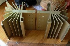
Peter Daniel said:I completed my new monoblocks as well, and I'm very happy with the amp; connected directly to a source (no line stage, no attenuator) this is probably the best amp I had in this system.
Disregard AC power connection, it's only temporary.
Nice work. I have been contemplating vertically oriented monoblocks myself. Less floor space, and maybe easier layout of parts inside with respect to connections to PCB, especially if separate input and output supplies are used (in a different amp). I think the top plate may look better rebated into top edge of heat sink, though. Also, you may consider raising the sinks off the footers to get better air flow through the fins, especially over the footers. Don't know about Plitron, but SumR has cans for their transformers with leads that come out on the top. If turned over, they can feed right through the top plate. Have you ever tried SumR toroids? Put some legs on the heat sinks, and a cased transformer, and give R2D2 a woody! Twins!
My interest for vertical amp chassis was certainly stimulated by that site: http://www.marklevinson.com/image_library/index.asp?categoryID=6&productID=12
I've heard about SumR but never used his products. A friend of mine does and seems to be happy.
I could trim the chassis details, but the idea was to build everything in one weekend. Besides, the amps will be sitting behind the wall, so I was not concerned with aesthetics that much.
I've heard about SumR but never used his products. A friend of mine does and seems to be happy.
I could trim the chassis details, but the idea was to build everything in one weekend. Besides, the amps will be sitting behind the wall, so I was not concerned with aesthetics that much.
http://www.conradheatsinks.com/technical-details.html
scroll down to: heatsink proportions.
scroll down to: heatsink proportions.
Re: F5 Heat Sink Dissipation
Hi, the house is still standing
1) after readjusting mfet spacing the temp was at 45c after three hours.
Keep in mind I'm testing in a 60f basement, and the sink is open on all sides i.e. no casing.
2) setting the bias was a snap, using thermistors & current limiters, and the bias is at 1.08amps and very stable. Today, I will adjust it to 1.2amps.
3) Fets spaced from edge to mounting holes is, 2"__3 1/2"__3 1/4"__1 3/4" .
Fets are 3/4" from top edge to top of fet. Clamps will only allow that
Yes, mounting the fets as per CViller, see below, should even out heat distribution and give cooler results. After running the amp upstairs in 68f~69f ambiant temp I'll check the temps again. I'm using a cheapo Cen-tech meter to measure the temps, I need to check the accuracy with an ice cube and boiling water as a range check. 0c--100c
re: CViller
The optimal vertical placement of the fets is 1/3 from the bottom, but I guess you already know that.
I think you might be pushing it by running two channels on one conrad sink - when you put the whole thing in an enclosing, the sinks will loose some efficiency and even worse if you place the amp in a audio furniture later on. Lowering the bias will give you more distortion.
--Now, last night I got my first earfull of the F5. Hooked up a pair of transformer coupled Strathearn ribbons, sans woofs. Very open and spacious. Next,
I wired up a pair of carbon fiber audax 5 1/4"s with a Dynaudio D21 tweet
in my old LS3.5a clone boxes. I cannot believe the bass, such as it is, coming out of these pip-squeeks.
I count my Borbely D100 w/3pairs mfets per ch. as my highest resolution amp. Well, the B-D100 sound stage is darker in comparison. The F5 lights up the stage. Resolution is much better this is working with a memory from a month ago, so. There is a much greater amount of instrumental information, little bitty sounds not resolved/heard are revealed.
Tympany hits reveal glorious details. This was the first random cd I played, a London 430 201-2 Berlioz 'Symphonie fantastic' Ceveland Orch.
So, today it's on to the Thor Seas, might sound too bright on these!? we'll see! And, a listen to those big disks with the little holes via thermionic devices, image density, a touch of warmth? Onward.
addendum-- Source was the Twisted Pair Buffalo Sabre dac direct in, crappy interconnects, 20gauge wires for speakers and one diode bridge on the power supply.
dcbingaman said:Ichiban - I'm dying to find out if the house burned down yet,
Three questions - 1) where did the temperature settle out at the FET's after a couple hours, 2) did the bias stabilize and at what current, and 3) how far apart, laterally, were your FET's, (I can't tell where the heck they are in the pictures). Also, do you think mounting them towards the bottom of the heat sink would have helped ??
Hi, the house is still standing
1) after readjusting mfet spacing the temp was at 45c after three hours.
Keep in mind I'm testing in a 60f basement, and the sink is open on all sides i.e. no casing.
2) setting the bias was a snap, using thermistors & current limiters, and the bias is at 1.08amps and very stable. Today, I will adjust it to 1.2amps.
3) Fets spaced from edge to mounting holes is, 2"__3 1/2"__3 1/4"__1 3/4" .
Fets are 3/4" from top edge to top of fet. Clamps will only allow that
Yes, mounting the fets as per CViller, see below, should even out heat distribution and give cooler results. After running the amp upstairs in 68f~69f ambiant temp I'll check the temps again. I'm using a cheapo Cen-tech meter to measure the temps, I need to check the accuracy with an ice cube and boiling water as a range check. 0c--100c
re: CViller
The optimal vertical placement of the fets is 1/3 from the bottom, but I guess you already know that.
I think you might be pushing it by running two channels on one conrad sink - when you put the whole thing in an enclosing, the sinks will loose some efficiency and even worse if you place the amp in a audio furniture later on. Lowering the bias will give you more distortion.
--Now, last night I got my first earfull of the F5. Hooked up a pair of transformer coupled Strathearn ribbons, sans woofs. Very open and spacious. Next,
I wired up a pair of carbon fiber audax 5 1/4"s with a Dynaudio D21 tweet
in my old LS3.5a clone boxes. I cannot believe the bass, such as it is, coming out of these pip-squeeks.
I count my Borbely D100 w/3pairs mfets per ch. as my highest resolution amp. Well, the B-D100 sound stage is darker in comparison. The F5 lights up the stage. Resolution is much better this is working with a memory from a month ago, so. There is a much greater amount of instrumental information, little bitty sounds not resolved/heard are revealed.
Tympany hits reveal glorious details. This was the first random cd I played, a London 430 201-2 Berlioz 'Symphonie fantastic' Ceveland Orch.
So, today it's on to the Thor Seas, might sound too bright on these!? we'll see! And, a listen to those big disks with the little holes via thermionic devices, image density, a touch of warmth? Onward.
addendum-- Source was the Twisted Pair Buffalo Sabre dac direct in, crappy interconnects, 20gauge wires for speakers and one diode bridge on the power supply.
Re: Re: F5 build on one Conrad-151 hsink
Why do you say this? I think it may be the opposite. Has to due with air flow along the fins. If you heat up the air at the bottom, less temperature difference between the air and heat sink at the top.
cviller said:
The optimal vertical placement of the fets is 1/3 from the bottom, but I guess you already know that.
Why do you say this? I think it may be the opposite. Has to due with air flow along the fins. If you heat up the air at the bottom, less temperature difference between the air and heat sink at the top.
bobodioulasso said:http://www.conradheatsinks.com/technical-details.html
scroll down to: heatsink proportions.
That is indeed an issue with vertical. As is everything, there are pros and cons.
Hi,
the usual recommendation for location for small heat sources on a big sink is ~ 40% up from the bottom.
The ratios change as more devices are added in the vertical direction.
To get good dissipation from any sink, the temperature of the backplate should be near isothermal as it is when tested by the manufacturer. This requires the radius from [devices to extremities] / [backplate thickness] to be ~ 10:1
Very tall and/or very wide sinks cannot approach optimal isothermal conditions with few heat sources. Give the sink the best chance to achieve low operating temperatures. Thick paint, horizontal fins, enclosed sinks, sinks sitting on carpets, facing down sinks, facing up sinks, dust build up on the dissipating surfaces, etc. can only increase operating temperatures.
rhysh said:Just a quick check up. Should These thermal pads be okay for the F5?
Those are the exact pads I'm using to good result. Of, course Papa says mica and silicone paste are best
http://www.bergquistcompany.com/objects/data_sheets/PDS_SPK10_0305E.pdf
ichiban said:
Those are the exact pads I'm using to good result. Of, course Papa says mica and silicone paste are best
http://www.bergquistcompany.com/objects/data_sheets/PDS_SPK10_0305E.pdf
Thanks for the heads up. Are you using thermal compound?
- Home
- Amplifiers
- Pass Labs
- F5 power amplifier