Peter Daniel said:Those are beryllium oxide pads which are discontinued now. Mouser carries aluminum oxide pads which are similar.
Do you use thermal grease with them ?
F5 Heat Sink Dissipation
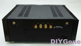
Ichiban - I'm dying to find out if the house burned down yet, because I'm planning on attempting the same crazy $#@* with a D-988 amp case, (see photo). The Conrad MF35-151.5 has a thermal capacity of ~ .2 degrees C / W. Using my expert photometric capabilities and scaling by fin area, the D-988 amp has about the same fin area and thermal capacity per side - so I should get the same results. According to Pass, at idle, each FET will need to dissipate ~30 watts, so your heat sink should be about 25 degrees C above ambient.
Three questions - 1) where did the temperature settle out at the FET's after a couple hours, 2) did the bias stabilize and at what current, and 3) how far apart, laterally, were your FET's, (I can't tell where the heck they are in the pictures). Also, do you think mounting them towards the bottom of the heat sink would have helped ??
Attachments
I intended to use MP930 in passive filtering between caps and I though I had 0.15Rs. When I started setting bias I couldn't understand why it only went up to 1.2A and when I decided to measure power output it appeared that the amp was giving me 4W only. Then I checked the rails and they were around 5V, so I figured out the power resistors were in fact 15R not 0.15R")
In feedback I have 2 x 150R Caddock MK132 per side. I use Rikens for JFET drain and in parallel with trimpot (2k7). I used those because I already had them and didn't see a reason why not give 'em a try.
In feedback I have 2 x 150R Caddock MK132 per side. I use Rikens for JFET drain and in parallel with trimpot (2k7). I used those because I already had them and didn't see a reason why not give 'em a try.
Re: F5 build on one Conrad-151 hsink
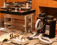
Nice pictures of your setup!
The optimal vertical placement of the fets is 1/3 from the bottom, but I guess you already know that.
I think you might be pushing it by running two channels on one conrad sink - when you put the whole thing in an enclosing, the sinks will loose some efficiency and even worse if you place the amp in a audio furniture later on. Lowering the bias will give you more distortion.
ichiban said:Finally got to test the boards on one Conrad MF35-151.5 heat sink to test its
ability to cool two F5s for a possible balanced configuration. If it is too hot,
Nelson has commented that the bias could be reduced to lower hs temp.
The amps biased up easily enough. The current is 1.1775A on each mfet, {0.683v/0.58ohms}. So far, after two hours the temps range from 61°C, 57°C, 50°C going from the center of the hs to the edge.
As can be seen in the pics the mfets are clamped high up on the sink and the middle two could be separated more. Also, the ambient basement temp is 15.6°C {60°F}.
Hope to give a listen on junk drivers tonight and if it's behaving maybe hook them to a pair of Seas Thors fed directly with the Buffalo Sabre/Ivy w/volumite.

Nice pictures of your setup!
The optimal vertical placement of the fets is 1/3 from the bottom, but I guess you already know that.
I think you might be pushing it by running two channels on one conrad sink - when you put the whole thing in an enclosing, the sinks will loose some efficiency and even worse if you place the amp in a audio furniture later on. Lowering the bias will give you more distortion.
amp-guy said:How do you like it compared to...........
Well, I can only compare to a GC that I was using during last few years and the F3 that I've been using for over a year now as well.
When I tried Aleph 30 couple years ago, I admired the midrange quality but the highs were lacking and I never went back to this amp again.
F3 was interesting right from a start, but I found that the output coupling cap was a limiting factor and if I didn't do anything about it, I wouldn't be probably using that amp either. With cap modification, the amp is very smooth, relaxing and detailed. I have it in my main system, with A75 at bottom end, and I couldn't be asking for more.
When I listened to F5 first time, I thought pretty good, but probably not good enough to replace GC, another wasted effort
Then I thought why not removing all the parts that are not really needed and off went current limiting circuitry: the amp opened up and instead of boring became much more interesting and involving, to a point that I spent whole evening listening to it.
Just to make sure that I'm hearing things right, I put GC back in a system and suddenly I understood what Srajan meant when talking about "leading edges"
The outlines of the tones are much better defined with F5, GC is softer here and it almost feels like distortion. The F5 also exceeds in tonal purity: all the sounds have more substance. Comparing to F3, it is more intense amp, which also requires better match of the rest of a system.The amp is so interesting now, that after 2 years rest, I put my TT rig back into use this evening....
Attachments
Peter Daniel said:
Then I thought why not removing all the parts that are not really needed and off went current limiting circuitry: the amp opened up and instead of boring became much more interesting and involving ...
I hardly understand how come the sound has been opened up after romoving the current limiting circuitry. The Q5 and Q6 are off, doing nothing, till the amp see the maximum current, say about 10A
I know you have a special ears diferrent from the ordinary people, tho . . .
Cheers,
>>
<<I know.
"Current limiting gets a bad rap in general, but I think it¡¯s a matter of where and how the limits are set. If you build this amplifier, you are of course welcome to delete this portion of the circuit, and of course you will not complain if a shorted output lets the smoke out of your amplifier. As it is, you will still be taking some chances with a shorted output."
And, I have both with and without the current limiting circuit
>><<
"Current limiting gets a bad rap in general, but I think it¡¯s a matter of where and how the limits are set. If you build this amplifier, you are of course welcome to delete this portion of the circuit, and of course you will not complain if a shorted output lets the smoke out of your amplifier. As it is, you will still be taking some chances with a shorted output."
And, I have both with and without the current limiting circuit
>>
<<Re: F5 Heat Sink Dissipation
You forgot to look at the Conrad spec sheet and particularly the de-rating information.
When DeltaT is less than the test value used by the manufacturer then the sink MUST be de-rated according to the manufacturer's graph or formula.
When the heat source is connected to one small area of the sink instaed of spread across the whole heatsink area the sink must be de-rated for the temperature drop to the extremities. Again manufacturers give some guidance on this.
I suspect that two devices on a wide Conrad sink that is rated @ 0.2C/W will rise not 25degC, but more like 35 to 40degC.
no.dcbingaman said:The Conrad MF35-151.5 has a thermal capacity of ~ .2 degrees C / W. Using my expert photometric capabilities and scaling by fin area, the D-988 amp has about the same fin area and thermal capacity per side - so I should get the same results. According to Pass, at idle, each FET will need to dissipate ~30 watts, so your heat sink should be about 25 degrees C above ambient.
You forgot to look at the Conrad spec sheet and particularly the de-rating information.
When DeltaT is less than the test value used by the manufacturer then the sink MUST be de-rated according to the manufacturer's graph or formula.
When the heat source is connected to one small area of the sink instaed of spread across the whole heatsink area the sink must be de-rated for the temperature drop to the extremities. Again manufacturers give some guidance on this.
I suspect that two devices on a wide Conrad sink that is rated @ 0.2C/W will rise not 25degC, but more like 35 to 40degC.
most transistors operate well with Vbe ~ 600mV.Babowana said:
I hardly understand how come the sound has been opened up after romoving the current limiting circuitry. The Q5 and Q6 are off, doing nothing, till the amp see the maximum current, say about 10A
I know you have a special ears diferrent from the ordinary people, tho . . .
Cheers,
>>
But they start to turn on @ ~ 400mV.
That reduces the trigger point for the current limiting to ~ 2/3 of set current.
This lower limit should be just above the maximum current you expect your load to demand.
For a 25W into 8ohm speaker expect maximum output voltage ~20Vpk.
This can generate up to 7Apk into a reactive 8ohm speaker.
Some recent posts have suggested that reactive speakers are more demanding than generally assumed in the past. If this is the case then maximum current could approach 5times what the nominal speaker impedance may lead you to expect.
If you have a particularly demanding speaker that demands upto 12Apk from a 25W amplifier and the protection transistors are starting to turn on @ ~ 6A then expect there to be some audible effect.
It looks to me that the set point for the current protection should be raised from 10Apk to 18Apk or more to remove this audible effect.
- Home
- Amplifiers
- Pass Labs
- F5 power amplifier