woodturner-fran said:OK, so I done some more testing. First up was to check out Q1/Q2. I made up the circuit that someone posted a little back up here (Idss) - and I got 10mA for SJ74 and 9mA for SK170. So it would seem that they were alive still.
Next I decided to look at the current limiting circuit. I removed all the components from the circuit as detailed earlier in the thread. Now I found I could get the bias set ok across R11 and 12. Its set as 0.6V on both but my offset at the speaker terminals is high. The mosfets are heating up nicely, but they aren't that hot. I've left it on for a little while and will go back and check it again. The offset I'm seeing is "floating" ie moving around a good bit while the bias values seem pretty stable. I get 4.4-4.6V G-S on Q3 and 4 and I meaure 16V D to S on Q1 and 2.
Does this sound OK?
Fran
that's OK
now re-read Papa's procedure in F5 pdf and set it .
once finally set - offset is rock stable
Nope, this ain't right.
OK, so I start with P1/2 at 0R. Turn on amp and make sure I have +/-24V rails. Then I alternately adjust P1/2 in small increments (1/2 turn each). I have 2 DMMs hooked up, one each across R11 and R12. Both of these read 0mV.
Nothing happens for the first few turns, then I see <10mV across R11 and R12. adjust a bit more and I get up to 100mV quickly enough.
But heres what I see then - after a certain point, if I adjust P1, the mV across R11 and R12 both increase. Its like as if P1 or P2 each controls the mV across both R11 and R12. All this time, if I stop and take a measurement across the speaker outputs, its floating anywhere from 100mV to 3,4,5 V.
I must be wrong in how I'm doing this... it can't be this difficult can it?
I double checked all the resistors and they all are the correct value (nice of dale to print the R on each one). The mosfets are IR ones that I bought from jackinnj (tech-diy). If I get a chance I'll take a few photos later. Obviously I've made a boo-boo somewhere, just can't see it.
Fran
woodturner-fran said:Nope, this ain't right.
Nothing happens for the first few turns, then I see <10mV across R11 and R12. adjust a bit more and I get up to 100mV quickly enough.
But heres what I see then - after a certain point, if I adjust P1, the mV across R11 and R12 both increase. Its like as if P1 or P2 each controls the mV across both R11 and R12. All this time, if I stop and take a measurement across the speaker outputs, its floating anywhere from 100mV to 3,4,5 V.
Fran
R11 and R12 should go up in tandem. P1 is Bias voltage, P2 is DC offset (DC on speakers). You should be able to slowly ramp up Bias and then get the DC offset down along the way. You dont need you speaker hooked up to do this. Just measure out to ground.
My advice --- I would have one DMM on R11 and one reading offset.
~.5v and <.02v offset, you should hook up your speaker and test.
Make sure you speaker didn't get shorted. Measure with ohm meter, and make sure that it reads something <10ohms.....
Good luck

Fran,
Both P1 and P2 are bias pots. Put one meter on R11 and one meter on speaker outputs. Bring up P1 until you have 50mv or so on R11 then turn P2 until the offset goes back down around zero. Then back to P1, turn up some more then bring offset back down. Keep repeating until you have R11 up around .600V and zero offset, then let it cook awhile and recheck.
Bill
ok, I concentrated on one channel. I have it sitting at around 0.5V and 40mV offset. I ran out of time then, so thats as far as I got, but I had it on for about 25mins or so and brought it up slowly. The plan is to do the same now with the other channel. If I can get both to around those figures then I'll try see does it play music.
Thanks to everyone so far for the help. The question still now remains over the current limiting part - maybe I might be able to reinstall those now (once I know its all working ok).
Fran
Thanks to everyone so far for the help. The question still now remains over the current limiting part - maybe I might be able to reinstall those now (once I know its all working ok).
Fran
woodturner-fran said:The question still now remains over the current limiting part - maybe I might be able to reinstall those now (once I know its all working ok).
The current limiting parts (or lack thereof if I understand you correctly) shouldn't have any effect on setting bias and adjusting for low DC offset. I left it out as well as the thermistors. Without the thermistors, it takes a while for the bias to stabilize, so you might be adjusting for awhile. I might put them in to make things easier on power up.
edit: Choky....we're always posting at the same time, you got some kind of sixth sense?
woodturner-fran said:ok, I concentrated on one channel. I have it sitting at around 0.5V and 40mV offset. I ran out of time then, so thats as far as I got, but I had it on for about 25mins or so and brought it up slowly. The plan is to do the same now with the other channel. If I can get both to around those figures then I'll try see does it play music.
Thanks to everyone so far for the help. The question still now remains over the current limiting part - maybe I might be able to reinstall those now (once I know its all working ok).
Fran
current limiting parts - hardly that they're schorched , but in any case - test little bjts with Hfe tester on your DMM ;
what's playing with you now is lack of thermistors ;
even if you certainly didn't fried them ( no way with that PSU voltage
 ) - check them in cold ( for your piece of mind ) and solder them back ;
then biasing da thing will be piece of cake
woodturner-fran said:......
So I could just add back in the thermistors without the other current limiting parts?
Fran
yup
you can put back current limit if you are sure that bjts are alive
Finished my F5
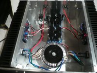
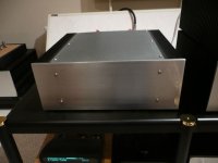
I finished my F5 with CViller's power supply and amp pcb's to keep my pair of F4's company. It went together really easily and biased up with no problems at all. Thanks Christian and Papa for this little gem!
Antek toroid, TSHA 22k uf caps, PRP resistors, etc. Nothing fancy.
Tom
I finished my F5 with CViller's power supply and amp pcb's to keep my pair of F4's company. It went together really easily and biased up with no problems at all. Thanks Christian and Papa for this little gem!
Antek toroid, TSHA 22k uf caps, PRP resistors, etc. Nothing fancy.
Tom
Attachments
Re: Finished my F5
")
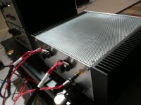
you have place and sink capacity for two more channels in that case ....
tms0425 said:I finished my F5 with CViller's power supply and amp pcb's to keep my pair of F4's company. It went together really easily and biased up with no problems at all. Thanks Christian and Papa for this little gem!
Antek toroid, TSHA 22k uf caps, PRP resistors, etc. Nothing fancy.
Tom
you have place and sink capacity for two more channels in that case ....
Re: Re: Finished my F5
I do have a few more F5 boards and a couple tubes of Mosfets just in case. One F5 should be fine for the CD/waveguide mid/tweet of my CS2's with Pumpkin @15db to balanced mono F4's on bass.
Just keeping my options open for higher power F6, F7, ...F99 or whatever...Zen Mod said:
you have place and sink capacity for two more channels in that case ....
I do have a few more F5 boards and a couple tubes of Mosfets just in case. One F5 should be fine for the CD/waveguide mid/tweet of my CS2's with Pumpkin @15db to balanced mono F4's on bass.Re: Finished my F5
Nice work on the amp.What is ther mesh made from on the top of your amp ? Looks like a good option for ventilation and economy.
dave
Nice work on the amp.What is ther mesh made from on the top of your amp ? Looks like a good option for ventilation and economy.
dave
tms0425 said:I finished my F5 with CViller's power supply and amp pcb's to keep my pair of F4's company. It went together really easily and biased up with no problems at all. Thanks Christian and Papa for this little gem!
Antek toroid, TSHA 22k uf caps, PRP resistors, etc. Nothing fancy.
Tom
- Home
- Amplifiers
- Pass Labs
- F5 power amplifier