Re: Re: firing up but fuse blowing
The apparent resistance accross + - 24 / 0 is about 40-50Ohm for both channels, so I don't know whether a short would be. The voltage across R11 and 12 is 0 for both channel, but for left channel the current through +24 -24 is 0 and for right channel the current reaches 1.5A at when rail voltage is as low as + - 2 V.
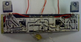
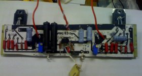
Attached is picture of a mian board. I printed PCB layout on paper, pasted it on perforated board, and followed traces. I checked a couple times with oringinal schematics and can't find what is wrong.....
I'd appreciate any help!
cviller said:Sounds like you have a short or have connected your power fets wrongly (if connected wrong, they are just power diodes). Try monitoring the voltage across the source power resistors (r11 and r12) when you turn up the voltage slowly. Otherwise post some detailed pictures and people in here might be able to help you.
The apparent resistance accross + - 24 / 0 is about 40-50Ohm for both channels, so I don't know whether a short would be. The voltage across R11 and 12 is 0 for both channel, but for left channel the current through +24 -24 is 0 and for right channel the current reaches 1.5A at when rail voltage is as low as + - 2 V.
Attached is picture of a mian board. I printed PCB layout on paper, pasted it on perforated board, and followed traces. I checked a couple times with oringinal schematics and can't find what is wrong.....
I'd appreciate any help!
Attachments
yes. I had mica insulations between Mosfet and Heatsinks.bubba177 said:rdk845--are the boards mounted to a heatsink when you blow a fuse?
Re: Re: firing up but fuse blowing
LOL, CVILLER, how would you compare the sound of the F5 to your J-Fish? I'm afraid to admit I etched and stuffed your JFish boards, but still haven't connected them (2SJ109BL sitting there wasted).
The task that poses the biggest obstacle for me is drilling and mounting to heatsink, so after having all those problems lining up the output device holes for my F4 and A30 (6 per channel), I started to procrastinate but I did build an F5 (at least to running state).
RDK845: I'm sure you can already see this question coming but are you sure the back traces are not touching the heatsink?
cviller said:
If I had to get the boards manufactured, I might throw in another layer to reduce board size, but then the old farts in here might have troubles stuffing the boards.
LOL, CVILLER, how would you compare the sound of the F5 to your J-Fish? I'm afraid to admit I etched and stuffed your JFish boards, but still haven't connected them (2SJ109BL sitting there wasted).
The task that poses the biggest obstacle for me is drilling and mounting to heatsink, so after having all those problems lining up the output device holes for my F4 and A30 (6 per channel), I started to procrastinate but I did build an F5 (at least to running state).
RDK845: I'm sure you can already see this question coming but are you sure the back traces are not touching the heatsink?
Re: Re: Re: firing up but fuse blowing
Yea. I have stand offs between heat sinks and boards. Measurs discontinuisty, when I disconnect the current limiter between PSU ground and chassis.twitchie said:RDK845: I'm sure you can already see this question coming but are you sure the back traces are not touching the heatsink?
and an other f5 pcb design ")
Hello everyone,
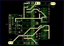
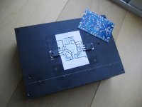
Past few days i've been buzzy designing my own F5 PCB. Quite interesting because its the first time i really tried. I used DipTrace.
I'm wondering if anybody is willing to take a look at it. My main goal is it to make it the same size as Peter's F4 PCB's and locate the FETs on the same position so i can easily fit it in a F4 chassis.
few notes/questions:
- i intend to use cadock resistors in he signal path
- i want to have PCB's professionally made, that's why i used two layers (any suggestions where i can have a few samples made without paying the jackpot...)
- small traces are 1mm thick traces are 4mm. is this enough?
- does anybody know where i can get get those nice blue Panasonic .47r and 100r 3watt resistors in europe.. or does anyone have some spares i could buy?
thanks in advance!!
cheers,
c.
Hello everyone,
Past few days i've been buzzy designing my own F5 PCB. Quite interesting because its the first time i really tried. I used DipTrace.
I'm wondering if anybody is willing to take a look at it. My main goal is it to make it the same size as Peter's F4 PCB's and locate the FETs on the same position so i can easily fit it in a F4 chassis.
few notes/questions:
- i intend to use cadock resistors in he signal path
- i want to have PCB's professionally made, that's why i used two layers (any suggestions where i can have a few samples made without paying the jackpot...)
- small traces are 1mm thick traces are 4mm. is this enough?
- does anybody know where i can get get those nice blue Panasonic .47r and 100r 3watt resistors in europe.. or does anyone have some spares i could buy?
thanks in advance!!
cheers,
c.
Attachments
Re: Re: Re: firing up but fuse blowing
I think the sound of F5 is better than the jfish (babbelfish modified) and perhaps even better than the aleph j, but new toys are always more fun.
Your right channel appears to be shorted... try focusing on only one channel at a time - disconnect the right channel. Are you sure you haven't mirrored one of the channels?
twitchie said:
LOL, CVILLER, how would you compare the sound of the F5 to your J-Fish? I'm afraid to admit I etched and stuffed your JFish boards, but still haven't connected them (2SJ109BL sitting there wasted).
The task that poses the biggest obstacle for me is drilling and mounting to heatsink, so after having all those problems lining up the output device holes for my F4 and A30 (6 per channel), I started to procrastinate but I did build an F5 (at least to running state).
I think the sound of F5 is better than the jfish (babbelfish modified) and perhaps even better than the aleph j, but new toys are always more fun.
Originally posted by rdk845
The apparent resistance accross + - 24 / 0 is about 40-50Ohm for both channels, so I don't know whether a short would be. The voltage across R11 and 12 is 0 for both channel, but for left channel the current through +24 -24 is 0 and for right channel the current reaches 1.5A at when rail voltage is as low as + - 2 V. Attached is picture of a mian board. I printed PCB layout on paper, pasted it on perforated board, and followed traces. I checked a couple times with oringinal schematics and can't find what is wrong.....
Your right channel appears to be shorted... try focusing on only one channel at a time - disconnect the right channel. Are you sure you haven't mirrored one of the channels?
My main goal is it to make it the same size as Peter's F4 PCB's and locate the FETs on the same position so i can easily fit it in a F4 chassis.
I salute this idea!
Variac said:
I salute this idea!
Why? The board has only two transistors and this way is about the only bad way to place them...

Re: and an other f5 pcb design
Hi culture. Send me a pm, I have some .47 3W blue Panasonic for you (and I can do something for the 100)
culture said:Hello everyone,
- does anybody know where i can get get those nice blue Panasonic .47r and 100r 3watt resistors in europe.. or does anyone have some spares i could buy?
thanks in advance!!
cheers,
c.
Hi culture. Send me a pm, I have some .47 3W blue Panasonic for you (and I can do something for the 100)

cviller said:You are ok as well, but if you I have seen most people flip peter daniels boards the other way around.
stupid people

Originally posted by massimo
Hi culture. Send me a pm, I have some .47 3W blue Panasonic for you (and I can do something for the 100)
Thanks massimo, PM send!
i have decided i'm changing the the footprints of the ztx trannies, this footprint is asking for problems with my shaky hands
cheers,
c.
culture said:
stupid people
Thanks massimo, PM send!
i have decided i'm changing the the footprints of the ztx trannies, this footprint is asking for problems with my shaky hands
cheers,
c.
You should also consider making the holes for wire connections bigger, unless you have some fancy connectors.
Regarding the prototyping, you can try www.olimex.com/pcb/
cviller said:
You should also consider making the holes for wire connections bigger, unless you have some fancy connectors.
Regarding the prototyping, you can try www.olimex.com/pcb/
Hi cviller,
Well, those holes are definitely a thing that need my attention, i also want to get rid off the square holes.
square holes, round holes, through holes, inner diameter, outer diameter.....this pcb designing thing is one big new adventure to me
cheers,
c.
Re: Re: Re: Re: firing up but fuse blowing
I have disconnected the left channel from PSU and taken out the right channel board from heat sink. It seems short on right channel is gone but now there is no current going through the board from + and - 24 rail. 10mA at 20V. there is no voltage across R11 and 12 regardless of P1 and P2 value. I replaced JFETs but the same results. Should I replace the Mosfets also? Except the bias voltage across R11 and R12, which voltage can I measure to see what's going on...
The left and right channels boards are identical looking from top.
Thanks for your help!
cviller said:Your right channel appears to be shorted... try focusing on only one channel at a time - disconnect the right channel. Are you sure you haven't mirrored one of the channels?
I have disconnected the left channel from PSU and taken out the right channel board from heat sink. It seems short on right channel is gone but now there is no current going through the board from + and - 24 rail. 10mA at 20V. there is no voltage across R11 and 12 regardless of P1 and P2 value. I replaced JFETs but the same results. Should I replace the Mosfets also? Except the bias voltage across R11 and R12, which voltage can I measure to see what's going on...
The left and right channels boards are identical looking from top.
Thanks for your help!

- Home
- Amplifiers
- Pass Labs
- F5 power amplifier