Bill Fuss said:I'm not sure I understand all of that. R10 measuring 7.5K showed you your jfets were toast, but if your new ones are OK you still have a problem with bias and offset. If both channels are biased the same then the temp will be the same, there is no magic involved.
Bill
Not sure, I set the bias on both amps and the temps seem the same now.
I guess my question is, would it be better that the jfets matched as a set of quads (for both amps) rather than just a single amp?
In my case one pair on one amp is 7.0ma and the other pair on the other amp is 8.2ma. Does this really matter?
Thanks
Thermos
Bill Fuss said:Glad things are working out.
I dont think matching jfets in this amp is very important, but it cant hurt. If you can hear the difference I would really like to hear about it. I just used what I had in BLs and it sounds stellar.
Best, Bill
Thanks for all your posts Bill, they have been really helpful.
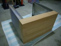
finished H/S for F5
Well they are almost finished. The sides need straightening up where they will butt up against the front plate/slab.
They measure 270mm High x 380mm Deep x 25mm thick, if you look at this pic.
The front plate is 430mm Wide x 270mm High x 60mm Thick
I'm actually worried that the heat will peel the varnish off the wood.
Attachments
i am planning on building this amp using 2x AMB regulated PS´s (one dedicated per channel) in a separated enclosure for the 2 ps modules and then using 2 power cords to power the amp modules on their own enclosure. but i dont know how the grounding should be arranged....any recommendation?
mekanoplastik,
From your link:
"Onboard heatsinks can be used which would allow the σ22 to supply up to 1A continuous (with much higher peak currents). More sustained currents are possible by using larger, offboard heatsinks."
They are too small. They don't have the current capacity needed.
From your link:
"Onboard heatsinks can be used which would allow the σ22 to supply up to 1A continuous (with much higher peak currents). More sustained currents are possible by using larger, offboard heatsinks."
They are too small. They don't have the current capacity needed.
Ed LaFontaine said:mekanoplastik,
From your link:
"Onboard heatsinks can be used which would allow the Ã22 to supply up to 1A continuous (with much higher peak currents). More sustained currents are possible by using larger, offboard heatsinks."
They are too small. They don't have the current capacity needed.
Hi Ed...
from same link "The high-current MOSFETs are not normally the limit of how much current the σ22 PSU could supply, as long as they are adequately heatsinked. "
and i plan on using an overkill heatsink
") ....and one PS per channel.....
....and one PS per channel.....do you think it would be possible?
I would wish it would work. However, another note of concern I read in the link provided says:
"... specified for many headphone amplifiers, preamplifiers, and power amplifiers up to around 20Wrms power output into 8Ω."
The F5 working in class A will draw continuous current far in excess of 1 A or 20 W rms. I remain skeptical it will work (very long). I did not find the "overkill heatsink" you refer to.
Regulation may be of limited value since the current draw is continuous. Papa Pass doesn't do his that way.
Another sign of concern: The parts list includes a transformer rated for 80 VA. The recommended transformer for the A5 is in the range of 400 VA.
Ed LaFontaine said:Papa Pass doesn't do his that way.
I thought that reducing voltage fluctuation across the output devices was part of Papa's Stasis trick.
Question is : What's the use of regulated rails if the amp itself switches to AB operation beyond 2 1/2 amps output current.
Maybe if you put Eight F5's per channel in a 4x2 parallel bridged setup.
Question is : What's the use of regulated rails if the amp itself switches to AB operation beyond 2 1/2 amps output current.
I thought regulation is not so important in class A as current draw is constant?
Wow!
I just made the F5 this weekend and I must say I'm very impressed. After having done a detour of Aleph J and a gainclone (kinda of a must for diy people to try out), I had a Saturday alone (no distractions), so I drew, etched and populated my new F5. Yesterday I fired it up, adjusted and listened. Great amp! Thanks NP.

One thing I noticed right away was the clarity in high frequencies and the detail of instruments.
My pcb is single sided and I didn't care too much about wire placement, but assembly was easy anyways. If anyone wants a bw version just drop me an email. The board is 105x50mm and the distance between power fets holes is 80mm.
I just made the F5 this weekend and I must say I'm very impressed. After having done a detour of Aleph J and a gainclone (kinda of a must for diy people to try out), I had a Saturday alone (no distractions), so I drew, etched and populated my new F5. Yesterday I fired it up, adjusted and listened. Great amp! Thanks NP.
One thing I noticed right away was the clarity in high frequencies and the detail of instruments.
My pcb is single sided and I didn't care too much about wire placement, but assembly was easy anyways. If anyone wants a bw version just drop me an email. The board is 105x50mm and the distance between power fets holes is 80mm.
Attachments
- Home
- Amplifiers
- Pass Labs
- F5 power amplifier