defect9 said:
you can build most of the power supply on the terminals of the caps. Literally lay it out like you see in the PS schematics (which are in the user manual for the F5, available at firstwatt.com in the product section)
I find power supplies easier to build than almost any other part of amps, so I'll pop in and do whatever I can to help you.
-Jared
Hehe, I'm not scared of building the PS from scratch (hence the rolley eyed smiley), but I'll admit I've never done it.
Thanks for the offer to help Jared, I'm sure we will be having many a conversation on here.
I've read everything there is to read on PassDIY and FirstWatt, but there are some concepts that still escape me. I can solder pretty good, and can stumble my way through a schematic alright, but things like matching fets and setting biases I'm not to keen on. Either way this will be fun (as long as you guys don't kick me out of the forum first for asking too many stupid questions down the road...
 )
)-Justin
There are no stupid questions, only stupid people. Those not smart enough to ask questions when they need help would qualify if you ask me. The only way to find out how to do it is to jump in and try. If you can solder and read a schematic, you can build these amps. When you get stuck, ask. I used to call myself "and electrical idiot". I now have 6 functional Pass DIY projects at home. All are awaiting enclosures. I have a Bridgeport and lathe and full wood shop, so no excuse other than I would rather build circuits. I think I am addicted to building electronics.
Jump in, the water is fine.
Jump in, the water is fine.
Re: Lost in Sarcasm
Of course not, i asked a second opinion.
Naah, just kidding, i can still remember your amp project from a couple of years ago.
vdi_nenna said:You know I was kidding?
Of course not, i asked a second opinion.
Naah, just kidding, i can still remember your amp project from a couple of years ago.
Attachments

I had a second look at Tino's balanced circuit :
http://www.diyaudio.com/forums/showthread.php?postid=1485677#post1485677
Suppose we only connect R1 ro R12 directly but without connecting to R2 or R11, and then for R2 directly to R11 without connecting to R1 or R12, would that not be an X-Topology ?
Patrick
http://www.diyaudio.com/forums/showthread.php?postid=1485677#post1485677
Suppose we only connect R1 ro R12 directly but without connecting to R2 or R11, and then for R2 directly to R11 without connecting to R1 or R12, would that not be an X-Topology ?
Patrick
Patrick,
I'd say no, at least along the lines of the SuSy patent we need inverting gain stages, having positive inputs too (if you think opamp-style), which are coupled together then to form the SuSy config.
One can rearrange the F5 to inverting config (mirroring the front-end currents to the opposite rail) and in fact I successfully tried that in simulation (with my BJT front-end variant), but I was unable to modify it into a SuSy config which would actually improve things over the simple bridge. But I didn't try too hard and maybe missed something important...
TimS' variant of a cross-coupled bridged F5 is quite nice I have to say, I simmed it (both JFET and BJT variants) and due to the cross coupling it also works well with unbalanced inputs (unlike a simple bridge). There is only some loss in headroom, but distortion performance doesn't seem to be affected.
BTW (and to those who have built/measured the circuit -- including Nelson), I seem to have found a potential stability problem with very capacitive speaker cables (say, several nanofarads). The overshoot seems to reach some scaring tens of dB's, much more than the slight rise that is there with plain resistive load (as reported, also in accordance to my sims). Jackinnj has proposed parallel caps to the feedback resistors (dropping gain to unity for HF), but those don't give signifigant improvment. For me using a series RC parallel to the I/V-resistors gave better results, dropping open-loop gain, introducing a pole and a zero to it (at ~20kHz and 200kHz, resp), pretty good damped response with any cap load. Another option would be the classical L//R at the output to isolate the capacitive load. Just my 2cts...
- Klaus
DaveM said:There are no stupid questions, only stupid people. Those not smart enough to ask questions when they need help would qualify if you ask me. The only way to find out how to do it is to jump in and try. If you can solder and read a schematic, you can build these amps. When you get stuck, ask. I used to call myself "and electrical idiot". I now have 6 functional Pass DIY projects at home. All are awaiting enclosures. I have a Bridgeport and lathe and full wood shop, so no excuse other than I would rather build circuits. I think I am addicted to building electronics.
Jump in, the water is fine.
Thanks for the encouragement Dave! I'm ready to jump, so I'm guessing the first step is to keep on reading, and to wait for the boards to become available through Pass DIY. I'm hoping there will be a group buy for matched fets or something, hehe!
-Justin
> I'd say no, at least along the lines of the SuSy patent we need inverting gain stages, having positive inputs too (if you think opamp-style), which are coupled together then to form the SuSy config.
I am not sure I'd entirely agree with that.
The essence of the X-topology, as far as I understand, is to feed the residual distortion of one half of a bridged amp to the other half for cancellation in differential mode, even if you can see them in common mode. It is not restricted to inverting amps, although it is easily implemented in an inverting amp configuration.
What I "proposed" would, IMHO, provide that cross-feedback. The main problem is (differential) DC stability, as the junction from R1 to R12 and R2 to R11 should be floated and not grounded. But maybe it is not a problem if the inout FETs are well coupled thermally.
Patrick
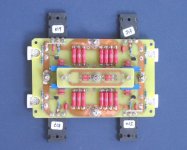
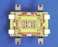
Balanced Version with Toshiba MOSFETs
My PRP resistors arrived from the States Thursday evening.
After a few hours of soldering, setting bias, running the normal square wave and frequency response tests, etc., I have been listening to one channel for a few hours now.
Quite listenable. A touch on the bright side, but surprisingly tight bass. Source for the quick test was headphone output from Micromega Stage 1, via battery powered DRV134 for balance conversion. Loudspeaker was B&W CDM1 with (DIY) Mundorf Crossover.
Circuit is similar to the balanced version posted by Tino.
Rails are +/- 16V, total bias 4A.
JFETs are matched 2SK170BL/2SJ74BL running at 5mA.
Output MOSFETS are 2SK1530/2SJ201.
Source resistor 0R22 & 0R18 respectively.
Here are a few photos.
Attachments
Hi Patrick,
I completly agree to your definition of "X", indeed one doesn't restrict oneself to inverting gain stages. It's all about wether or not the error signal of one half is feed into the other with the correct polarity and level.
I simulated all three variants, the simple Bridge (the nodes in question grounded), Zinsula (nodes connected directly) and yours (nodes cross-connected only). But I couldn't find any significant change in distortion, both looking at the single-ended outputs (ref'd to GND) and the differential ouput, the third harmonic always dominated THD with its stable value. Therefore I guess that the error signal is not cross-fed in the way needed to get the cancellation in the diffential output.
Quoting the Master, an indicator if "X" is at work should be:
This does not seem to be case in either of the floating node configs. We have to think harder
- Klaus
I completly agree to your definition of "X", indeed one doesn't restrict oneself to inverting gain stages. It's all about wether or not the error signal of one half is feed into the other with the correct polarity and level.
I simulated all three variants, the simple Bridge (the nodes in question grounded), Zinsula (nodes connected directly) and yours (nodes cross-connected only). But I couldn't find any significant change in distortion, both looking at the single-ended outputs (ref'd to GND) and the differential ouput, the third harmonic always dominated THD with its stable value. Therefore I guess that the error signal is not cross-fed in the way needed to get the cancellation in the diffential output.
Quoting the Master, an indicator if "X" is at work should be:
Original by Nelson Pass
By actual measurement, this circuit does very little to reduce the
distortion and noise of each half. Distortion curves before and after the application of Su-Sy are nearly identical. The distortion curves for the circuit shown in the patent cover sheet are: (A) the intrinsic distortion of each half of the real example circuit, (B) the distortion of the differential output lowered due to the intrinsic matching between the circuits, (C) the distortion of each half with Su-Sy applied, and (D) the differential distortion with Su-Sy applied.
This does not seem to be case in either of the floating node configs. We have to think harder
- Klaus
Measurements :
There is a very small peak of +0.5dB at about 600kHz, but since it was not proper power supply and wiring, I did not bother and left it as is.
Full complements to the original circuit creator that it works first time without a hitch, even with all the changes from the original schematics.
Patrick
There is a very small peak of +0.5dB at about 600kHz, but since it was not proper power supply and wiring, I did not bother and left it as is.
Full complements to the original circuit creator that it works first time without a hitch, even with all the changes from the original schematics.
Patrick
Attachments
Patrick,
pretty cool job you did, congratulations! And thumbs up to Nelson of course, there aren't many simple 4-Transistor amps around that seem to be as good and as robust as this one.
BTW, did you run tests with cap loads yet?. I'd be very interessted to see how the step response looks like...
- Klaus
pretty cool job you did, congratulations! And thumbs up to Nelson of course, there aren't many simple 4-Transistor amps around that seem to be as good and as robust as this one.
BTW, did you run tests with cap loads yet?. I'd be very interessted to see how the step response looks like...
- Klaus
Re: Balanced Version with Toshiba MOSFETs
Darn man, that is simply too neat, to be true.....
Lovely stuff..
EUVL said:[B
Here are a few photos. [/B]
Darn man, that is simply too neat, to be true.....
Lovely stuff..
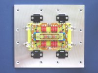
EUVL said:Fully assembled :
Thats even better; I think I see 4 power J-fets in there?? Wrong pic?
- Home
- Amplifiers
- Pass Labs
- F5 power amplifier