Babowana said:Briefly read through . . .
Papa concludes at the end: "It sounds great."
Yes, mine, very similar one (of Papa's), sounds really excellent for me.
Be doing well, Papa.
JH
BABOZEN!!!

Zen Mod said:kind soul felt sorry to poor serbie , and sent me scan of article .....
nice little amp ;
May I please have a copy of the scanned pages; please. Thanks a million.
boyz n' girls
I was cheatin' and I received that scan ;
I can't spread it further , except in case that Papa give his blessings
( no - he did not send me scan , but article is primary his ) .
btw -I really sent mail to AX , asking for pdf subscription .
just be more patient and I'm sure that Papa will post that circ
Zen Mod said:I can't spread it further ...
I agree with you at 101%.
I don't know whether I have any quality to talk about Papa.
Simply amazing! He could see all details, find small things
and make them big . . . and make smiles behind the mustache
hiding the meaning of the smiles where I can't look into . . .
But, at least I keep your meaningful word once given to me,
"Don't worry, They will be busy bad-mouthing your work . . ."
JH

Vix said:Ok, waiting...
In the meantime, is it too selfish to ask Papa to post his buffer schematic?
The charm of the buffer will perhaps not be appreciated without the
text commentary that comes with it. A little patience will be
required.
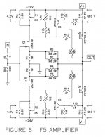
Nelson Pass said:Here is the schematic. It does not include, of course, the discussion
on the function of the additional parts or how the values are
derived or what tweaks will be useful. Those of you with a copy
of the article are free to comment as you like.


I wish AudioXpress would have offered a free .pdf download of the
article when a 1 year subscription was purchased - something creative
like that.
The schematic doesn't mean much to me without the article!")
Think how many new subscribers they could have gained!
back to being patient looking forward to the full article.
article when a 1 year subscription was purchased - something creative
like that.
The schematic doesn't mean much to me without the article!
Think how many new subscribers they could have gained!
back to being patient
looking forward to the full article.> Those of you with a copy of the article are free to comment as you like.
Yes I am one of the lucky ones who got a copy. No I have not read it yet.
Since no one is volunteering, I shall stick my neck out. Hope my interpretations are correct, and Nelson will forgive me for speaking my mind. And I shall only attempt to comment on the differences between the simplified and the full schematics.
Starting from the input.
R9 offers some isolation to the source. R10 provides ground reference when not connected. Just good practice.
The drain resistor was 600 ohm in the simplified, so 1st stage bias was 6mA. Since the second stage is now degenerated (R11,12), the bias voltage has to be increased to 4.2V. So drain resistor 700R required. This is formed by R3, P1 and (R15+TH1) in parallel. Similarly on the -ve side.
P1,2 provide bias adjustment, but I would replace them with fixed resistors after trimming at temperature. TH1,2 appears to be a themistors (NTCs) for bias compensation during warm-up, assuming positive tempco of the MOSFETs (should be the case for the FETS named and the 1.3A bias). If so, they want to be thermally coupled to the power MOSFETs.
I personally do not like thermal compensation with thermistors. For one, it changes the open loop gain, and you don't really know by how much. Worst, you don't know whether the 2 halves drift and compensate symmetrically. So I would just take TH1,2 out and use R15,16 only if I were to build. The consequence is a bit lower bias when cold, and a small risk of thermal run-away. But I have the same (no compensation) in Aleph-X and never have any problems. But that is purely my personal choice.
Q5, R19, R17, R21 are for over-current and over-voltage protection. There was something similar in the Aleph schematics. And I also saw something similar before from Kaneda.
When voltage across V19 exceeds 0.6V, Q5 will shut off the MOSFET by reducing gate voltage to zero. So current limit is set by R17 & R19, provided a value for R11 has been chosen. Voltage limit is set by R21, R19, in case of a output MOSFET failure, e.g. Not must have, but nice to have. And since it is placed further from the gate of Q3 than R13, it should have no negative influence during normal operation.
R11,12 are source degeneration for the MOSFETs. John Curl mentioned on the blowtorch thread that source degeneration messes up the distortion spectrum. But I guess you need something for bias stability (a sort of local current feedback). And it provides a convenient means for current sensing (for protection). I find 0R47 a bit high, and would have gone for 0R22 or even 0R1. But that also depends on a lot of things like which MOSFET and how much heat sinking.
I wonder if Nelson would care to explain his choice.
R13, R14 are gate stoppers for the MOSFETs (to prevent oscillation). The values are quite low, but then it is supposed to be a fast amp (see the 200kHz square wave), and the drain resistors are quite high (compared to e.g. Aleph-X). Something to experiment with.
R5//R7 gives 50R 6W for the feedback, and half the inductance of a single 3W resistor.
The only remaning question for me is :
If I wish to go balanced, should I just use two of these or should I use complementary diff pairs for the first stage and Xed feedback ?
Hope there were no mistakes / mis-interpretations, and Nelson forgives me for saying openly my personal preferances.
Patrick
- Home
- Amplifiers
- Pass Labs
- F5 power amplifier