ok using a scope for harmonics, how about if I also monitor my AWG output for harmonics to ensure its clean before taking anything away from the FFT result? Thats what I did in post #16532 which replicated Nelson's plot nicely.
Also I'm using a 14bit vertical scope now whereas the one used in post #16532 was 12bit
Also I'm using a 14bit vertical scope now whereas the one used in post #16532 was 12bit
You can first check your scope FFT with a reference oscillator, such as that from Viktor.
It is known to have harmonics below -150dB.
Just use the scope (or whatever analyser you have) to measure the Viktor and plot FFT.
That plot will tell you what distortion your scope / analyser has.
You will never be able to measure anything below that.
Just having 14 bit is not enough. My USB scope has 16 bit.
It also needs to have 1ppm linearity if you want to measure -120dB.
Or you use other tricks such as notch filters.
But there are other threads for those.
Cheers,
Patrick
I appreciate your advice, I'll do as you suggest. Regards Neilhow about
forget about using a scope to set P3. Instead using a DMM measure and match the resistance over R3 and R4 with amplifier off. This will centre P3.
If you want to scope the output for FFT ect then be absolutely sure your amp is ground referenced (F5 are), then make sure the probe earth only goes to output negative (-)..
I have been searching this forum but can’t find the help I need (most likely because my question is so basic/beginner). I am starting an F5 build along with the universal power supply PSU 3.0. For the F5’s power supply I have selected 22000 uF 35 V Aluminum Electrolytic Capacitors.
What would be an appropriate or best choice toroidal transformer? What would the specs be? Thank you to anyone that can help
What would be an appropriate or best choice toroidal transformer? What would the specs be? Thank you to anyone that can help
yes recently I was thinking the same Pat so thats the road I'm going to takeOr you use other tricks such as notch filters.
But there are other threads for those.
Cheers,
Patrick
What would be an appropriate or best choice toroidal transformer? What would the specs be? Thank you to anyone that can help
https://www.antekinc.com/as-3218-300va-18v-transformer/Good quality and reasonable price in th states.
Thanks Evan and Jedi. I wasn’t finding crap on Newark, digi key and mouser. The link is very appreciatedhttps://www.antekinc.com/as-3218-300va-18v-transformer/Good quality and reasonable price in th states.
For the F5 amplifier design I used a 500VA (13.5A max), x2 18V output, tiroidal transformer. If anything it has too much capacity and I needed to increase the fuse rating on the power supply to prevent intermittent fuse failure. It now works fine.I have been searching this forum but can’t find the help I need (most likely because my question is so basic/beginner). I am starting an F5 build along with the universal power supply PSU 3.0. For the F5’s power supply I have selected 22000 uF 35 V Aluminum Electrolytic Capacitors.
What would be an appropriate or best choice toroidal transformer? What would the specs be? Thank you to anyone that can help
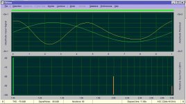
Today, despite wonderful weather I adjusted my revisited F5 with Toshibas SK and SJ first time with the P3 pot.
Wonderful I got H2 neg phase, H2 pos phase and H2 minimum compared to H3.
Astonishing how small the turn for P3 is to get the different H2 peaks! And there was no need for me to readjust the offset, because it changed only in a very small amount.
Wonderful I got H2 neg phase, H2 pos phase and H2 minimum compared to H3.
Astonishing how small the turn for P3 is to get the different H2 peaks! And there was no need for me to readjust the offset, because it changed only in a very small amount.
Attachments
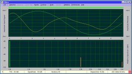
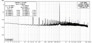
Here I tried to get the lowest distortion with low H2, not bad....
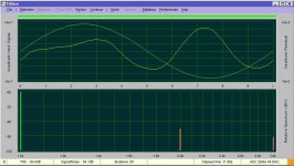
The sound with H3 dominant reminded me of the F1, these H3 amps talk a lot to the listener...
:--))
(There is a problem with the hum, I have to look....)
The sound with H3 dominant reminded me of the F1, these H3 amps talk a lot to the listener...
:--))
(There is a problem with the hum, I have to look....)
Attachments
Last edited:
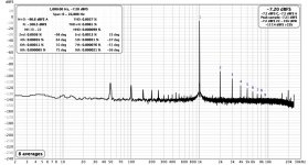
Then I tried to mimic the distortion and residual of the INT-25, means when I can believe the values stereophile showed, H2 10dB higher and neg phase.
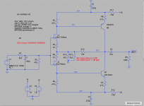
Therefore a made a small J-Fet pre with 6dB, often shown here in different versions in front of the F5. The pre alone seems to have pos H2 phase and a nice order of harmonics.
Therefore a made a small J-Fet pre with 6dB, often shown here in different versions in front of the F5. The pre alone seems to have pos H2 phase and a nice order of harmonics.
Attachments
I can't speak from experience with the F5, but with the BA3 pre, which has P3Yes, P3 is magic if you have the tools to adjust it.")
You can make adjustments using your ears.
A couple of turns, either way, makes a big difference to the sound and can be set to personal preference. 😊
(Nb. bias and offset need checking and altering after moving P3.)
Of course I had in Spice to take the models I found in real I took the more available ones.....and here the small 6dB pre I found in other threads, for 10dB gain add the 2k2 to the 4k7.
Spice: Q1 2SC1844 = real KSC1845
Spice: Q2 2SA970 = real KSA992
Hi, what source resistor values do you have in the output? (I have a //pair of 2SK176/2SJ56 without source resistors since several years, and while it is detailed it lost some charm. . .) so it is my once-in-a-while box now.Today, despite wonderful weather I adjusted my revisited F5 with Toshibas SK and SJ first time with the P3 pot.
Wonderful I got H2 neg phase, H2(H3?? al) pos phase and H2 minimum compared to H3.
Astonishing how small the turn for P3 is to get the different H2 peaks! And there was no need for me to readjust the offset, because it changed only in a very small amount.
- Home
- Amplifiers
- Pass Labs
- F5 power amplifier