difference in length - only if one is foot long , while other one 33foot long
Phew!....Now that is a relief to know!
Thanks Jeff, To be clear—run the left channel V+, GND, V- braid, towards speakers around the IEC side of the amp, instead of right across under the secondary wires. Will twist those secondaries as well.
I have also found that rotating the Antek transformer will affect noise. There is usually a position where the noise is less. In my experience, that position is where the wires exiting the transformer is not pointing towards the left and right channels. In your case, rotating the transformer so that the wires are at the 12 and 6 o'clock positions may be the best position.
Another suggestion is to route the AC from the IEC jack straight back to the transformer, running the wires under the PS board. This will place the AC away from the right channel board.
Another thing - I've always twisted 3 wire runs. According to the late AndrewT, twisted is the most effective way to keep loop area low.
3-wire power: twist or braid?
Here is another article on amplifier grounding. It is by diyAudio member Bonsai, and there are some easy reading practical suggestions at the end:
http://hifisonix.com/wordpress/wp-content/uploads/2019/02/Ground-Loops.pdf
Last edited:
Hey Guys,
Wasn't sure where to post this or if I should make a new thread—figured I'd keep it with the F5 thread in case anyone else can benefit from any proposed solutions. I considered rebooting some old threads—but no.
See pics. Let me know if more detail is required.
The quite audible buzz/hum sounds to me like what the transformer sounds like with ones ear in the case—definite "buzz", perhaps more than "hum", but both. It's just that it's coming through the speakers. Even under other audio, depending on volume and distance from the speakers of course. I'm tuned to it...so to me it's pretty annoying, and I can pick it out.
If I short the inputs, still have buzz/hum (this rules out environment correct?).
From other research and inputs from members—here's what I've tried:
- Connecting PCB grounds directly across the amp (ZenMod in some old thread)
- Connecting speaker grounds directly to PCB
- Connecting PCB grounds directly to star ground after CL-60 (this may not be a star ground—I've looked at so many drawings—it all starts to blur)
- Flipped the transformer—6L6 suggestion—still hums.
What I haven't tried is all of the above together, with the exception of the transformer flip. I saw an "if all else fails" drawing that showed all grounds from input/speakers/AMP boards/PSU board to a single grounding point on the chassis with a CL-60 in line to the IEC ground.
I'm going to replace the PSU to chassis CL-60, since it got a little toasty in a previous—now resolved—start-up attempt—it's visually discolored. I don't know if this could be a buzz/hum factor or not.
I also haven't messed with the input grounds based on some reading up here.
If I plug the amp into a preamp—B1K—I'd say the buzz/hum increases for a moment, then seems to return to normal—non-preamp hum.
The reputation of the F5 is that it should be quiet/silent... so I'd love to solve this? Anyone see anything—or have suggestions?
I'm going through this:
Audio Component Grounding and Interconnection
A lot of that article is a bit over my head at the moment...
Incidentally the Antek transformer isn't the shielded variety—I've read mixed things about this—but that it CAN matter—article above... I have another build in process—that one has a shielded Antek.. Should be interesting.
THX!!
Is it logical you have only one Led lighted on the PSU board ?
I think you can just measure the resistance across R3 and R4, and adjust P3
if necessary, to make them the same. (Should be around 9 ohms with P3=200R,
R3=R4=10R)
Well shoot, measured 18.3 across R3 and R4 on one board and 18 across the same resistors on the other board
Is it logical you have only one Led lighted on the PSU board ?
Thanks for all the suggestions so far guys/VERY helpful—and dare I say I keep learning—and well, that is the fun of it.
- Twisted the secondaries—hum persists.
- Will reroute the left channel per Jeff—requires a longer V- wire—which I'm also going to change out to yellow since it confuses me with a ground. Green was used in the build guide (sorry Jim!).
- Will also twist left side instead of braid—thanks for the bonsai article—that was in my notes list per 6L6—but I had yet to find it—haven't read it yet—I will.
- I'll also rotate the transformer
We will see what happens after all of this... If I run the power under the PSU from ICE, where would I locate the block? I may be able to squeeze it in between the transformer and the PSU if I move the transformer L bracket one hole back—that will fit, but it's max..
If I were to be super super picky I might be able to say the hum/buzz is slightly greater from the left channel than right....! That pushes the issue in the direction of Jeff's comment about the diode bridge being the noisemaker. er... should I be considering a PSU rotation? Not sure about fitment there...
well , that is the glory path of using 300mm deep one, instead of 400 
few rules I have :
-use biggest case I can manage/buy/afford
-always route mains bellow (elevated by 10mm distancers) base plate
-all connections to safety gnd on one screw at base plate near IEC
-Donut with static shield and magnetic screen (nothing more than few turns of same strip they're using for cores)
-everything at secondary and DC side symmetrical , which means bridges around/near Donut , input to cap bank ditto to bridges, wires to pcbs then left and right
-solid core tiny twisted from input jacks to pcbs in not exactly shortest but neatest I can arrangement
-output wires - GND terminal closer to RCA , hot further from RCA
-pray before flipping da switch
so , to cut harrasing ya , can you rotate that PSU pcb for 90, CCW?
well , that is the glory path of using 300mm deep one, instead of 400
few rules I have :
-use biggest case I can manage/buy/afford
-always route mains bellow (elevated by 10mm distancers) base plate
-all connections to safety gnd on one screw at base plate near IEC
-Donut with static shield and magnetic screen (nothing more than few turns of same strip they're using for cores)
-everything at secondary and DC side symmetrical , which means bridges around/near Donut , input to cap bank ditto to bridges, wires to pcbs then left and right
-solid core tiny twisted from input jacks to pcbs in not exactly shortest but neatest I can arrangement
-output wires - GND terminal closer to RCA , hot further from RCA
-pray before flipping da switch
so , to cut harrasing ya , can you rotate that PSU pcb for 90, CCW?
This all makes sense. I'm glad I chose the glory path!!!!! You are setting my AJ build up for success here—I have a 400mm deep case for that one!!!
For F5—I have the baseplate raised (Thanks 6L6)—would you locate the terminal strip under the baseplate? Assuming yes. I could do this. ZM—in your opinion should I try any of the other ideas first? Or just pull it out and reconfigure per your list above best I can (non-shielded transformer). I think I can make it fit—just.
"Tiny" wires? I've used 22ga solid for signal—I have some cat5 wire (24ga I think?)—would that be better?
When you say "all connections to safety ground on one screw" is that PCB, PSU, and IEC grounds to one screw? or signal and output grounds too (don't run them to PCB)?
And flip my speaker jacks? "output wires - GND terminal closer to RCA , hot further from RCA"
Hope you are okay with me asking for clarifications! I'm learning.... I have had a lot of laughs now for some time reading your posts—I think you took it easy on me! Thanks.
well, if you really insist , I can mock ya all day long ...... at least 'till the moment when I usually faint in my chair
see my builds (blog in my sig) and all will be clear
-terminal strip on top of base plate , near Donut ; if on bottom - too close to bottom cover , safety nill
-I didn't read all other tips , sorta sleepy so easy to be confused ; try easiest ones , that's good for elevating your anxiety treshold ...... simply because easiest is usually least efficient ...
-tiny for me is solid core 0.25mm Dia and less
-all connections hich needs to go to safety ground - one from IEC , one from static shield of Donut (if exists) , one from audio GND on cap bank pcb (through NTC of course)
-in your case , you're using shitty WBT so close together , so no use of flipping
I think rotating that pcb would help in shorting/sorting/unifying power paths and maybe some Donut rotating .......
have fun!
well, if you really insist , I can mock ya all day long ...... at least 'till the moment when I usually faint in my chair
see my builds (blog in my sig) and all will be clear
-terminal strip on top of base plate , near Donut ; if on bottom - too close to bottom cover , safety nill
-I didn't read all other tips , sorta sleepy so easy to be confused ; try easiest ones , that's good for elevating your anxiety treshold ...... simply because easiest is usually least efficient ...
-tiny for me is solid core 0.25mm Dia and less
-all connections hich needs to go to safety ground - one from IEC , one from static shield of Donut (if exists) , one from audio GND on cap bank pcb (through NTC of course)
-in your case , you're using shitty WBT so close together , so no use of flipping
I think rotating that pcb would help in shorting/sorting/unifying power paths and maybe some Donut rotating .......
have fun!
Haha. I can take it. Get some rest. Or... just get more coffee. Or?
What's not shitty????(WBT) I want to know! I didn't get those for AJ. Recommendations please.
Thx.
I like Polklemme, PKNI 10 B Series, 63 A, 60 V, Vernickelte Kontakte, Panelmontage, Hirschmann
if nothing else , I sleep better , giving decent money to Old Guard , not any money to fancyschmancy Yuppies
")
Thanks!! no Yuppies!
well, if you really insist , I can mock ya all day long ...... at least 'till the moment when I usually faint in my chair
see my builds (blog in my sig) and all will be clear
-terminal strip on top of base plate , near Donut ; if on bottom - too close to bottom cover , safety nill
-I didn't read all other tips , sorta sleepy so easy to be confused ; try easiest ones , that's good for elevating your anxiety treshold ...... simply because easiest is usually least efficient ...
-tiny for me is solid core 0.25mm Dia and less
-all connections hich needs to go to safety ground - one from IEC , one from static shield of Donut (if exists) , one from audio GND on cap bank pcb (through NTC of course)
-in your case , you're using shitty WBT so close together , so no use of flipping
I think rotating that pcb would help in shorting/sorting/unifying power paths and maybe some Donut rotating .......
have fun!
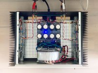
Hey ZM!!! Guess what has improved MASSIVELY!!!!! ????
(Image)
I didn't do everything on your list... because then I would learn less—less fast.
Now—HUM is gone. Vanished. This is with the amp plugged in, no source. What remains is a faint BUZZ. I need to reread the section from the Bonsai article (that's where the tying together the input grounds came from) to see what's next. And you smart people may beat me to it—or have other things to try. I hope I left the ground wires from the PCBs long enough to reach the star ground—it's tight in there now.
When I plug in the B1K as source—things get a little louder, buzz, a little hum—some microphony from the B1K (that dissipates). Now, here's what's interesting about the preamp in the mix—at the volume low—the hum/buzz is pretty audible—seems to be more than the current layout F5 alone—but WAY less than with the previous internal F5 layout. When I up/max the volume on the B1K, the buzz/hum level returns to what I'm hearing with the amp alone (perhaps even a tad less?)—that is to say—a little buzz to still deal with. ???
NP is on record someplace saying that the F5 ("3rd harmonic beast") is likely a good pairing with the B1K—correct me if I'm wrong.... So I'm wondering about it all anyway.
To pull this off with the family setting I need a least 2 inputs plus a volume control.
Thanks guys for all the suggestions!!! Huge improvements here. FUN. Setting the AJ build up for success.
(Would smaller gauge wires for the inputs be a factor here, at all? I'm still a little lost on wire sizing and its effects.)
Attachments
Plug in a single channel from the B1K. Louder buzz or hum? If not, it's a ground loop being completed by the ground in your B1K. If so, it might be the B1K itself producing the buzz/hum.
With the B1K plugged in are you saying the buzz/hum is less with the volume maxed than with it at minimum?
With the B1K plugged in are you saying the buzz/hum is less with the volume maxed than with it at minimum?
Plug in a single channel from the B1K. Louder buzz or hum? If not, it's a ground loop being completed by the ground in your B1K. If so, it might be the B1K itself producing the buzz/hum.
With the B1K plugged in are you saying the buzz/hum is less with the volume maxed than with it at minimum?
Hey Jeff,
Wow. I wasn't sure if the B1K should be on or not. Just did the following:
- Amp on (slight buzz, equal in both speakers, per previous post).
- Add just the right channel input from B1K (off) —buzz goes away completely from right speaker, can still hear buzz from left speaker
- Switch the above and try just the left channel from B1K —buzz faint from left channel, and also audible in right, but louder.
I will revise what the B1K volume is doing. Adding the preamp to the chain increases the noise overall—it's a buzz and a shhhhh (plus the microphony that dissipates), as the volume goes up the buzz gets less, the shhhh gets louder!
I will also experiment with the how everything is plugged in. That Bonsai article is pretty gold. I have cables all over the place in test mode—though the buzz from the amp alone is still something else I believe.
I CANNONT stress enough how much better this has gotten with the rev internal layout. The remaining buzz was inaudible by a 9-yr-old from 3-4' away (expert hearing)—so I'm being nitpicky and maybe what I'm hearing is "normal"....Is it possible that the amp also sounds better overall? Placebo effect? Expectation bias? Haha....
Is it possible that the amp also sounds better overall?
Yes, of course. There's less noise, and a reduction in noise is an increase in signal integrity. You're not dreaming.
- Home
- Amplifiers
- Pass Labs
- F5 power amplifier