")
Trouble with board
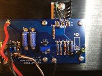
Hi, I'm building a standard F5 using DIYAudio Cviller V3 boards and have had a bit of trouble at the biasing stage. On board is happy with no voltage on the source resistors pots set to zero. The other board has 44V on R7 , R8 is presently sitting at 350mV, no smoke or hot resistors. I checked the 5K pots pre install for O Ohms and have endlessly turned the pots up and down P1 has not effect, P2 does alter the voltage on R8. Any ideas on what is wrong and why I have rail to rail voltage on R7? Photos attached. Thanks in advance.
Hi, I'm building a standard F5 using DIYAudio Cviller V3 boards and have had a bit of trouble at the biasing stage. On board is happy with no voltage on the source resistors pots set to zero. The other board has 44V on R7 , R8 is presently sitting at 350mV, no smoke or hot resistors. I checked the 5K pots pre install for O Ohms and have endlessly turned the pots up and down P1 has not effect, P2 does alter the voltage on R8. Any ideas on what is wrong and why I have rail to rail voltage on R7? Photos attached. Thanks in advance.
Attachments
 all are ok ?
Hi, I am using ZTX transistors at Q5 (550) and Q6 (450) they are correctly positioned and oriented (I've checked again) and I checked all solders with a magnifying glass as I made the board.
The JFETs are from DIYAudio store and the MOSFETs are Vishay from RS Electronics.
Should I order some spare transistors (Spencer has some JFETs)?
The JFETs are from DIYAudio store and the MOSFETs are Vishay from RS Electronics.
Should I order some spare transistors (Spencer has some JFETs)?
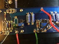
Ok, fresh try after frying one channel, almost frying the second one too....but Aniket put some sense in me to use bulb based current limiter that seems to have worked....
Transformer 2 X 18V, 400VA
Bulb 60W
PS- DiyAudioStore with 10000 uF X 8 caps
F5 pcb V3 - DiyAudioStore
The heatsink is heating, no smoke, things looking good, but wanted to understand next steps before removing the bulb jig. With .40 V on R7,R8, the bulb glows bright...guess it is drawing large current...the bulb goes off around .12V on R8
Sent from my iPhone using Tapatalk Pro


go back with Iq , remove bulb tester , power on , set everything again
however , do not go for more than 60% of final Iq , considering that heatsinks are laying face down
final settings need to be made when case is completed and everything in place , including top lid - temperature equilibrium is one of major requirements for final settings
however , do not go for more than 60% of final Iq , considering that heatsinks are laying face down
final settings need to be made when case is completed and everything in place , including top lid - temperature equilibrium is one of major requirements for final settings
Thanks 6L6 and Sound happy.
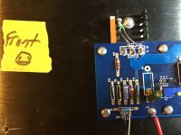
I've looked at the boards on 5mm standoffs well clear of any wires/solder, also checked the MOSFETs and an number of leads around the boards no short to ground.
The board is removed and the other side is biasing up well. What next? I just know you are going to get me to pull and measure the transistors.
....The board is removed and the other side is biasing up well. What next?....
@ Steve
Your good working side can be useful for detection of the problem.
I always power up two channels ( if nothing smoke haha ) trimmers at the same resistance on both.
Open F5 schematic.
Now test step by step from input to output DC voltages around all components .
Note mesurements on paper so you can compare, verify after with good working channel.
Jfets and semiconductors are electrostatic sensitive devices take care manipulate them without fingers touch on his pins.
Have a nice day

Attachments

- Home
- Amplifiers
- Pass Labs
- F5 power amplifier