I think that the measurement largely also reflects the damping factor of
the amplifier, and the amp with higher DF will simply have less of the
tweeter's distortion showing up at its output. It doesn't necessarily
speak to the distortion of the amplifier or the actual distortion of the
acoustic output of the tweeter.
the amplifier, and the amp with higher DF will simply have less of the
tweeter's distortion showing up at its output. It doesn't necessarily
speak to the distortion of the amplifier or the actual distortion of the
acoustic output of the tweeter.
Just share, for those that don't have access to a distortion analyzer.
I managed to set the P3 on my F5 board using a simpler setup.
Laptop, Behringer UFO202 Audio Interface and RightMark Audio Analyzer software.
The caveat is to have a attenuation circuit and a dummy load.
So you have have a 100 ohm resistor in series with a 100k Trimmer Potentiometer, take the output from the variable residence pin and solder it on a female rca connector.
An last not least put this circuit in parallel with the dummy load.
in my case the use of P3 did bring the total THD from 0.05 to 0.002 ( peaking at 6W ), for sure my setup isn't super accurate however but looking at cost benefit isn't bad.
PS. having a oscilloscope helps a lot, but a good digital multimeter do the job.
Last edited:
What wattage are the resistor and trimmer?
1/4 w... the use of a low power 100 ohms resistor is to protect the trimmer.
This would save you a little soldering.
http://www.diyaudio.com/forums/atta...guide-building-pass-f4-amplifier-img_1789.jpg
http://www.diyaudio.com/forums/atta...guide-building-pass-f4-amplifier-img_1789.jpg
Doubt that was the intended purpose of the P3 but hey, whatever blows your hair back...
P3 is to adjust the negative feedback. that's P3 purpose to reduce the distortion.
P3 adjusts the relative open loop gain of the two halves, + and - of the
amplifier. In so doing it adjusts the amount and phase of 2nd harmonic.
Generally you will find the lowest distortion number at the point where these
two are balanced out, nulling the 2nd harmonic, leaving mostly third.
amplifier. In so doing it adjusts the amount and phase of 2nd harmonic.
Generally you will find the lowest distortion number at the point where these
two are balanced out, nulling the 2nd harmonic, leaving mostly third.
This one has a 2.2k R15 -
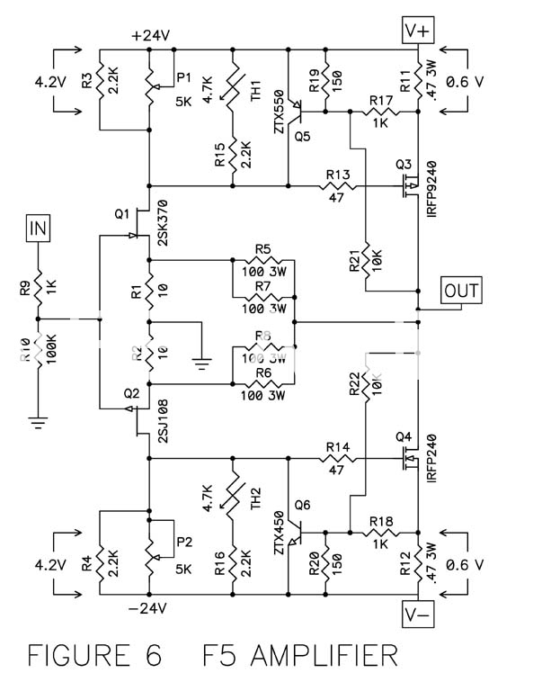
you have original schematic for F5 but later Mr. Pass provided tweaked values for R21, R22 etc. 10 K replaced with 22 K
Last edited:
I believe 2.2K not 22K.you have original schematic for F5 but later Mr. Pass provided tweaked values for R21, R22 etc. 10 K replaced with 22 K
would you please tell us value for FQA12P20 degen resistor to match N device
I would like to refine F5 sound and try to trim charecteristic of both front and output devices
for front I will do Patrick trick 4 - 5 R degen for P device but not sure for output device degen resistor to add to 0.47 R
I would like to refine F5 sound and try to trim charecteristic of both front and output devices
for front I will do Patrick trick 4 - 5 R degen for P device but not sure for output device degen resistor to add to 0.47 R
Here are the fairchild devices. the slopes differ by ~6% -- I regressed the data starting with 100mA
Follow-up to hum problem post #15422
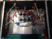
Thanks to everyone for their suggestions. I tried almost all of them: checked all grounds, moved wires around, lots of different grounding configurations. Was about to take it all apart and try the HBR method when I thought I'd unbolt the transformer and stand it on its edge, perpendicular to chassis base. And voila, no hum. So I got a fairly sturdy right angle brace from the hardware store and bolted the transformer onto that. I also cleaned up all the wiring I'd messed up while trying different configs. Turned it back on and the hum was back but very faint and only in the left channel. Moving the left side output wiring towards the center cured that, see picture. So my hum is gone or at least to a point that I can't hear it. Woohoo! Listening to it now with my "test" Focal Chorus 714v speakers. Sounds great. My next step will be to add the speaker protection PCB. Thanks again everybody.
Thanks to everyone for their suggestions. I tried almost all of them: checked all grounds, moved wires around, lots of different grounding configurations. Was about to take it all apart and try the HBR method when I thought I'd unbolt the transformer and stand it on its edge, perpendicular to chassis base. And voila, no hum. So I got a fairly sturdy right angle brace from the hardware store and bolted the transformer onto that. I also cleaned up all the wiring I'd messed up while trying different configs. Turned it back on and the hum was back but very faint and only in the left channel. Moving the left side output wiring towards the center cured that, see picture. So my hum is gone or at least to a point that I can't hear it. Woohoo! Listening to it now with my "test" Focal Chorus 714v speakers. Sounds great. My next step will be to add the speaker protection PCB. Thanks again everybody.
Attachments
Dbis,
you have used twsted pairs for the flow and return virtually everywhere.
That twisting helps make the amplifier less susceptible to picking up hum interference.
However I see big loops at your inputs. You should see whether reducing the area of these loops has any effect on hum pick-up. You could reduce the loop area to less than 10% of what shows at present.
After that the three widely spaced power wires are creating big loops. You can run the wires closer to the board to reduce loop areas.
I see some black and red single wires between the caps and the transformer.
Do these pass any varying current?
Last edited:
Hi Andrew,
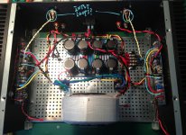
I really appreciate your feedback. I just want to make sure I'm getting it right. When you say input loops are you referring to the blue circled areas on the attached image? And for the loops in the power supply wires, are they the single wires(red, yellow, black) right before the amp boards? I've highlighted them in blue. To get them closer to the boards should I try to twist them together some more and take out some of the slack?
The single red and black wires (yellow and black on minus side) between the transformer and the psu are the wires coming from the bridge rectifiers to the psu board. Should those be twisted and shortened as well?
Thanks again
Attachments
I am surprised that rotating the ring core transformer changed your hum so much. Is your hum 50 Hz or 100 Hz?Thanks to everyone for their suggestions. I tried almost all of them: checked all grounds, moved wires around, lots of different grounding configurations. Was about to take it all apart and try the HBR method when I thought I'd unbolt the transformer and stand it on its edge, perpendicular to chassis base. And voila, no hum. So I got a fairly sturdy right angle brace from the hardware store and bolted the transformer onto that. I also cleaned up all the wiring I'd messed up while trying different configs. Turned it back on and the hum was back but very faint and only in the left channel. Moving the left side output wiring towards the center cured that, see picture. So my hum is gone or at least to a point that I can't hear it. Woohoo! Listening to it now with my "test" Focal Chorus 714v speakers. Sounds great. My next step will be to add the speaker protection PCB. Thanks again everybody.
Yes, you are reading me correctly.Hi Andrew,
I really appreciate your feedback. I just want to make sure I'm getting it right. When you say input loops are you referring to the blue circled areas on the attached image? And for the loops in the power supply wires, are they the single wires(red, yellow, black) right before the amp boards? I've highlighted them in blue. To get them closer to the boards should I try to twist them together some more and take out some of the slack?
The single red and black wires (yellow and black on minus side) between the transformer and the psu are the wires coming from the bridge rectifiers to the psu board. Should those be twisted and shortened as well?
Thanks again
The loop areas between Flow and Return halves of the pairs should be kept very small to minimise interference.
I don't know how much effect it will have on your amplifier. The changes could be unmeasurable.
I was measuring the effect on a long "ground" trace in an amplifier that had +ve supply and -ve supply on opposite sides of the PCB. The ground trace had to run around the perimeter of the PCB. The 2mVac/div showed up an enormous interference waveform on the scope as the probe was placed at different points on this long trace.
The input signal was being corrupted by the long "ground" trace. I scrapped the DX PCBs. I have had other PCBs that repeat this error.
Last edited:
I believe it's 120Hz. I don't have anything to measure but seems too high a pitch to be 60Hz. Before rotating there was a buzzy hum in the transformer as well as the speakers. After rotating you could still hear it in the transformer but not the speakers. Strange. Maybe the magnetic field changes. I'm not quite sure how that works but I saw some drawings online showing how the magnetic field manifests itself around the ring and out from the center. So I thought maybe changing the orientation might change the way the wires are affected. You have to get within a few inches to hear the transformer and once in the chassis with lid on and in the audio rack it's really hard to hear.I am surprised that rotating the ring core transformer changed your hum so much. Is your hum 50 Hz or 100 Hz?
I saw some drawings online showing how the magnetic field manifests itself
around the ring and out from the center. .
First Watt routinely rotates their amplifiers' toroids for minimum noise in production.
Jfet discrepancy?
Apologies if this is an old topic, but I have searched and not found any info. I have recently finished build of F5 amp using v3 boards/schematic. When I first powered up to set bias things went bad..... R7 and R8 lit up and Q1 and Q2 popped. Some other resistors are also showing discoloration. I have checked values of parts and correct placement and everything appears to check out alright. I am suspicious of Q1.....I am using a 2sj108 jfet, purchased from Ebay (first mistake) Looking at data sheets between toshiba, philips, and Vishay the drain source and gate are in a different order. As well the toshiba is listed as a P channel, where the Vishay is listed as an N channel. The manufacturer of ebay part is unknown.....
Does this seem possible? Same part number with different pin allocation? Has anyone run in to this before or am I just losing it! In mean time I have ordered LSJ74 and LSK170's but am still a little nervous that it won't light up again!
I did use volt meter set to check diodes to test the ebay jfets (spares, not cooked ones) and the N channel, Q2 2sk370 checked out as I think it should.. pos probe to gate and get same readings with neg going to drain or source. When testing Q1-2sj108 I had different results.... I expected same readings with pos/neg probes reversed. What I found/think I found was the gate is in location of source and seems to be an N channel FET.
I am not sure how accurate of a test that is but it sure looks like I have wrong Jfet.
Any input would be greatly appreciated!
Gordr,
Check every jFET before you fit.
FETs come off the production line with an enormous variation in parameters. You can't just randomly pick any and just hope it will work as a previous build.
Measure the Idss of every jFET. See they all fall within the range stated in the manufacturer's datasheet.
If they are from a dubious source, then also check the gm by measuring the Vpinchoff and calculating the gm. Again that must fall within the range shown on the datasheet. The gm does vary with Id, so you need to plot your value on the graph and see how close to the line they come.
If you want to buy from unknown sellers/crooks on Ebay you must be doubly sure you know what they have sold you. And initiate Fraud proceedings/claim if they are re-marked, or fakes.
I am aware of a few of our reputable Members selling via Ebay. Use them if you don't have access via the Forum.
There are a few disreputable Members selling on the internet. We have seen evidence of them selling fakes.
You need to be careful and use our Membership to obtain recommendations.
Last edited:
- Home
- Amplifiers
- Pass Labs
- F5 power amplifier