thanks guys..
I went with 3w at end.
so far I have one f5 assembled on a test heatsink with a biasing of 0.46 amp per mosfet .
It's a very simple and impressive amp.
My plan is to run some tests against the amp I use to drive my tweeters that is a P3A .. as the F5 will replace it.
So I was thinking to test the F5 vs P3A in a low power scenario like 3w and 7w, using the same tweeter and compare the distortions results from REW.
I guess I might need to increase the biasing to maybe 0.7amps .. my question to you guys is how the bias impacts the mosfet linearity? I meant what is the minimal biasing to have the F5 full potential to delivery 7W rms.
Last edited:
Yet another hum question
Hi all,
Firstly, I would like to thank everyone that helped me with my F5 (& DCB1): 6L6 for those invaluable build guides for newbies like me, Salas and Andrew with my DCB1, and countless others on the diyaudio site and Mr Pass for making it all possible. When I finally played some music on my F5 it was one of those rare audio moments when I could really hear a difference from my current Exposure 2010S2 integrated, which is no slouch BTW. The F5 sounded wonderful—so clear and natural—even through my $5 test speakers. I was giggling all by myself.
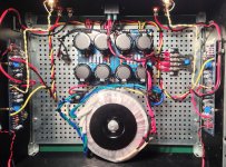
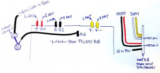
Alas, there’s just one niggling problem; the dreaded hum or in my case a what I would call a “hum-buzz” coming from the transformer, Antek AS-4218 (400VA 18V), which is also audible in the speakers as an almost imperceptible 120hz hum with a slightly buzzy edge. I didn’t notice it right away since I tested the channels separately. However, when everything checked out and I connected both channels, the noise happened. If I disconnect one channel, it goes away or is reduced to the point that I can barely hear it even though the transfo keeps buzzing. I eliminated the DCB1 as the problem by connecting one IC between the amps inputs: hum-buzz when connected, gone with either one disconnected. I assumed a ground loop. So after trying several things, rerouting and shortening wires, checking all the returns and grounds, different outlets and even Joffe’s HBRR & HBRL(thanks Andrew) to no avail I decided to move the transfo outside of the chassis. First thing I noticed is the transfo doesn’t buzz unloaded. Measured 19Vac on each secondaries unloaded and + and - 25Vdc on PSU(diyaudio PSU PCB v3 with two bridge rectifiers, Epcos 15000uf 50v x 8 caps). Once under load, transfo starts to buzz but no buzz through the speakers. Back in the chassis, transfo and speakers buzzing. Measured AC on speaker outputs and got between 4 and -2mVac at first but then settled right around 1 to 0mVac. I’m attaching a picture and drawing of how the returns and grounds are wired as well as chassis overview.
So, I guess my question is if I should put it down to a faulty transformer and contact Antek—there is one copper wire that seems to bulge out a bit more than the others— before going even further chasing the hum-buzz. Any advice would be greatly appreciated.
Thanks
Hi all,
Firstly, I would like to thank everyone that helped me with my F5 (& DCB1): 6L6 for those invaluable build guides for newbies like me, Salas and Andrew with my DCB1, and countless others on the diyaudio site and Mr Pass for making it all possible. When I finally played some music on my F5 it was one of those rare audio moments when I could really hear a difference from my current Exposure 2010S2 integrated, which is no slouch BTW. The F5 sounded wonderful—so clear and natural—even through my $5 test speakers. I was giggling all by myself.
Alas, there’s just one niggling problem; the dreaded hum or in my case a what I would call a “hum-buzz” coming from the transformer, Antek AS-4218 (400VA 18V), which is also audible in the speakers as an almost imperceptible 120hz hum with a slightly buzzy edge. I didn’t notice it right away since I tested the channels separately. However, when everything checked out and I connected both channels, the noise happened. If I disconnect one channel, it goes away or is reduced to the point that I can barely hear it even though the transfo keeps buzzing. I eliminated the DCB1 as the problem by connecting one IC between the amps inputs: hum-buzz when connected, gone with either one disconnected. I assumed a ground loop. So after trying several things, rerouting and shortening wires, checking all the returns and grounds, different outlets and even Joffe’s HBRR & HBRL(thanks Andrew) to no avail I decided to move the transfo outside of the chassis. First thing I noticed is the transfo doesn’t buzz unloaded. Measured 19Vac on each secondaries unloaded and + and - 25Vdc on PSU(diyaudio PSU PCB v3 with two bridge rectifiers, Epcos 15000uf 50v x 8 caps). Once under load, transfo starts to buzz but no buzz through the speakers. Back in the chassis, transfo and speakers buzzing. Measured AC on speaker outputs and got between 4 and -2mVac at first but then settled right around 1 to 0mVac. I’m attaching a picture and drawing of how the returns and grounds are wired as well as chassis overview.
So, I guess my question is if I should put it down to a faulty transformer and contact Antek—there is one copper wire that seems to bulge out a bit more than the others— before going even further chasing the hum-buzz. Any advice would be greatly appreciated.
Thanks
Attachments
To me it is not quite clear if the hum is induced by the trafo or a groundloop. You wrote that when disconnecting one input the hum stopped, which is clearly a loop afaik.
I know because I have the same bear under the lid
Did you try what is illustrated in post no 15333? (sorry too dumb for direct link)
I was too lazy, but will try out soon.
I know because I have the same bear under the lid
Did you try what is illustrated in post no 15333? (sorry too dumb for direct link)
I was too lazy, but will try out soon.
Hi all,
Firstly, I would like to thank everyone that helped me with my F5 (& DCB1): 6L6 for those invaluable build guides for newbies like me, Salas and Andrew with my DCB1, and countless others on the diyaudio site and Mr Pass for making it all possible. When I finally played some music on my F5 it was one of those rare audio moments when I could really hear a difference from my current Exposure 2010S2 integrated, which is no slouch BTW. The F5 sounded wonderful—so clear and natural—even through my $5 test speakers. I was giggling all by myself.
Alas, there’s just one niggling problem; the dreaded hum or in my case a what I would call a “hum-buzz” coming from the transformer, Antek AS-4218 (400VA 18V), which is also audible in the speakers as an almost imperceptible 120hz hum with a slightly buzzy edge. I didn’t notice it right away since I tested the channels separately. However, when everything checked out and I connected both channels, the noise happened. If I disconnect one channel, it goes away or is reduced to the point that I can barely hear it even though the transfo keeps buzzing. I eliminated the DCB1 as the problem by connecting one IC between the amps inputs: hum-buzz when connected, gone with either one disconnected. I assumed a ground loop. So after trying several things, rerouting and shortening wires, checking all the returns and grounds, different outlets and even Joffe’s HBRR & HBRL(thanks Andrew) to no avail I decided to move the transfo outside of the chassis. First thing I noticed is the transfo doesn’t buzz unloaded. Measured 19Vac on each secondaries unloaded and + and - 25Vdc on PSU(diyaudio PSU PCB v3 with two bridge rectifiers, Epcos 15000uf 50v x 8 caps). Once under load, transfo starts to buzz but no buzz through the speakers. Back in the chassis, transfo and speakers buzzing. Measured AC on speaker outputs and got between 4 and -2mVac at first but then settled right around 1 to 0mVac. I’m attaching a picture and drawing of how the returns and grounds are wired as well as chassis overview.
So, I guess my question is if I should put it down to a faulty transformer and contact Antek—there is one copper wire that seems to bulge out a bit more than the others— before going even further chasing the hum-buzz. Any advice would be greatly appreciated.
Thanks
Did you checked if you have any contact/conductivity from the mosfets pins to the heatsink?
this is first time building an amp using a diyaudio pcb.. I found interesting that the speaker output ground connects to the pcb. normally I connect it on the ground using a ground star schema.
Thanks guys. Weird that the post 15333 didn't show up in all my searching this weekend. It's probably the solution but I'm a little wary of cutting my board up just yet. Thanks for the info though. I did check continuity between mosfets and sinks before powering up but I'll check again 2nite. Also, rereading my post, I'm pretty sure I forgot a decimal on the output AC. The figures should be preceded by a "0." So really not much. I was hoping someone would say "Oh, it's your transfo. Send it back!" But more likely it's something I did so I'll keep searching.
what is the minimal biasing to have the F5 full potential to delivery 7W rms.
For 7W rms into 8R it's 0.935Arms, or 1.323A sine peak. This means a bias current of half that, 0.66A DC.
Last edited:
Borbely told us to bias our mosFET outputs to at least 500mA, irrespective of how many devices were in the output stage..................
I guess I might need to increase the biasing to maybe 0.7amps .. my question to you guys is how the bias impacts the mosfet linearity? I meant what is the minimal biasing to have the F5 full potential to delivery 7W rms.
This is because FETs don't have an optimal ClassAB output bias that minimises crossover distortion, unlike a BJT output stage. The crossover distortion quite simply becomes less as one increases the bias current, all the way up to full ClassA.
Rayma gives you the required minimum bias to achieve full ClassA into a resistive 8r0 dummy load.
A reactive speaker load particularly with a complex crossover, can demand transient currents approaching and even exceeding 3times what a resistive load will drive.
A ClassA amplifier is usually biased to drive the rated resistive load in full ClassA and the push-pull versions revert to ClassAB if current demand ever exceeds the ClassA current limit.
Last edited:
thanksBorbely told us to bias our mosFET outputs to at least 500mA, irrespective of how many devices were in the output stage.
This is because FETs don't have an optimal ClassAB output bias that minimises crossover distortion, unlike a BJT output stage. The crossover distortion quite simply becomes less as one increases the bias current, all the way up to full ClassA.
Rayma gives you the required minimum bias to achieve full ClassA into a resistive 8r0 dummy load.
A reactive speaker load particularly with a complex crossover, can demand transient currents approaching and even exceeding 3times what a resistive load will drive.
A ClassA amplifier is usually biased to drive the rated resistive load in full ClassA and the push-pull versions revert to ClassAB if current demand ever exceeds the ClassA current limit.
For 7W rms into 8R it's 0.935Arms, or 1.323A sine peak. This means a bias current of half that, 0.66A DC.
thanks
dbis, pictures needed. Take your soldering iron and go over all the ground connections and try moving the signal wires around some. Ground the inputs and see what happens.
Thanks wdecho. There's a photo in my first post, not very detailed though. I'll redo all my connections to ground, shorten some wires, and resend pictures if it still hums. When you say "ground the inputs" do you mean connect them directly to the PSU PCB ground rather than going back through the amp board? I'll try. I'm sure it's something simple.
Thanks guys. Weird that the post 15333 didn't show up in all my searching this weekend. It's probably the solution but I'm a little wary of cutting my board up just yet. Thanks for the info though. I did check continuity between mosfets and sinks before powering up but I'll check again 2nite. Also, rereading my post, I'm pretty sure I forgot a decimal on the output AC. The figures should be preceded by a "0." So really not much. I was hoping someone would say "Oh, it's your transfo. Send it back!" But more likely it's something I did so I'll keep searching.
related to your problem.
http://www.diyaudio.com/forums/pass-labs/121228-f5-power-amplifier-1191.html#post2923127
where should this link take us?
where should this link take us?
It takes me to post #11909
dbis, cut the wire to a RCA cable and tie the wires together and you will have ground the inputs. Then check for hum.
Thanks. I've already tried shorting plugs in each input. Is that what you mean? With shorting plugs there was no hum. I only get hum when I connect a source, preamp, iPhone, etc, or if I connect input to input with rca cable. If I disconnect one channel hum gone.
Looks like I'll take everything apart, shorten wires, check all joints. I do have couple questions for you guys though. When I put together the PSU, it took a long time to heat the pcb up to flow solder on the resistors and caps. I think it's because the traces are quite large. I'm pretty sure there are no cold joints. Could I have done anything at that stage to cause the hum in the transfo? My DC voltages, l/-25vdc unloaded, were ok though. Also, when biasing, the readings I was getting were constantly fluctuating by +/- a few mV. I assumed that was normal. Was it? Thanks again.
I had a similar problem in another amplifier that was also mosfet based, I tried re-wiring ... a lot of things... it uses a ground star schema... at the end the problem was that the mosfets were busted due to a connectivity with the heatsink.
So I fixed the mosfet insulation to the heatsink and replace all mosfets. and after that it worked fined. but remember this was a complete different amplifier... different pcb.. it was a ESP P101.
@dbis
what you describe is a ground loop.
I had the same problem with my F5.
Rerouting (experimenting) the ground wiring scheme helped a bit, but not entirely.
My final solution was a new transformer with four secondarys so its quasi dual mono
(the two channels share only the primary winding).
All is quiet now.
The price for a custom made former is not what most people think.
cheers
A.
- Home
- Amplifiers
- Pass Labs
- F5 power amplifier