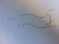
So, somebody here who can help me or has further more ideas where i have to place the hum breaking resistors?? The amp sounds already amazing, and I only hear the hum when my ears a very close to the speakers, but still, this drives me crazy, especially that nothing what I do has an impact on this
With a single power supply for both channels and a shared source, it is close to impossible to break the resultant ground loop. The RCA shields will *always* have higher impedance than the thick PSU wires and as a result you will get signal return currents to flow in the PCB power tracks. Then there is the obsession with star ground, which is the worst possible way to make any sort of construction.
I personally follow dual mono for 90% of my builds but in case I have to make a stereo amplifier, I route the speaker return to the power supply input on the amplifier PCB (NOT the PSU) and insert a very small (about 2 ohm) resistor between signal ground and this junction. For dual mono construction, this resistor is not needed and I still put the speaker return as close as possible to the signal references.
Note that in the case of a mains fault, the resistor can open and disconnect the RCA barrels from safety ground. You should ideally connect two 6-8A diodes and a small value capacitor across this resistor to prevent this. As is obvious, two such are needed, one for each channel.
It is critical that the current between power supply and speaker not be seen by the signal ground, hence the routing is important. It must return to the side 'behind' the speaker connection, and not between the two points or on the power supply side. You should not visualise 'ground' as a single point, but as a large number of mixed currents flowing along the paths you, the builder, set for them.
The other thing I do is insert a loop breaker between power ground and chassis ground. This eliminates the possibility of the signal return coupling through the safety ground between the source and amplifier. I usually use the standard 3-component circuit, but have also used just a thermistor with decent results. You'll find plenty of discussion on this thread about these solutions.
Depending on the sensitivity of your speakers and/or the power supply ripple, you can still have some audible hum. However if the problem is a ground loop (as you do have silence sometimes), these two things should fix it.
@McQuaide: Check your input JFETS, and add 470pF-1nF capacitors between gate and drain of each MOSFET.
R13 burning would indicate destructive oscillation, the one time I've seen burned outputs, a blown SK170 and fused emitter resistors. Oh, and none of the gate resistors survived either.
In addition to what ZM said, I would simply not put the two output devices back in. You can test the amplifier without the output devices, and check that turning the pots affects the gate voltage. Once you are satisfied, you can solder in the output devices, back down the trimmers to zero and start the biasing from scratch.
The standard F5 does not have an output Zobel, nor does it have any local supply rail decoupling.
It even omits conventional filtering of the input signal.
I often see reports of well behaving F5 suddenly going wrong.
Why?
I do question the lack of filtering, decoupling and Zobel loading and wonder if there is oscillation during some types of operation that eventually makes a component fail?
It even omits conventional filtering of the input signal.
I often see reports of well behaving F5 suddenly going wrong.
Why?
I do question the lack of filtering, decoupling and Zobel loading and wonder if there is oscillation during some types of operation that eventually makes a component fail?
the HBRR+HBRL reduce the interference current.So, somebody here who can help me or has further more ideas where i have to place the hum breaking resistors?? The amp sounds already amazing, and I only hear the hum when my ears a very close to the speakers, but still, this drives me crazy, especially that nothing what I do has an impact on this
When placed in the correct position this reduction in current results in a reduction in interference voltage. That is what you hear/measure at the output.
You need to compare the sch to the PCB and see what parts of the circuits are connected to those input pads.
Then work out where the added resistances need to be located.
As a temporary method of proving that HBRR works for your amplifier.
Attach your two interconnects. It should be quiet.
Connect the two remote barrels with a 20r resistor. This is the added resistance that reduces the interference current.
Measure/listen to the H+N.
Is it quiet, or quiet enough?
Connect one channel of a music source to one of the interconnects with the 20r still connecting the two barrels. Does the music come through without audible Hum?
The standard F5 does not have an output Zobel, nor does it have any local supply rail decoupling.
It even omits conventional filtering of the input signal.
I often see reports of well behaving F5 suddenly going wrong.
Why?
I do question the lack of filtering, decoupling and Zobel loading and wonder if there is oscillation during some types of operation that eventually makes a component fail?
I also switched to a tube preamp recently, a Bottlehead Foreplay. Not sure if the F5 didn't like something coming in.
@McQuaide: Check your input JFETS, and add 470pF-1nF capacitors between gate and drain of each MOSFET.
R13 burning would indicate destructive oscillation, the one time I've seen burned outputs, a blown SK170 and fused emitter resistors. Oh, and none of the gate resistors survived either.
In addition to what ZM said, I would simply not put the two output devices back in. You can test the amplifier without the output devices, and check that turning the pots affects the gate voltage. Once you are satisfied, you can solder in the output devices, back down the trimmers to zero and start the biasing from scratch.
Is anyone selling individual JFETS for the F5 or would I need to get a full kit from the store?
@McQuaide: Check your input JFETS, and add 470pF-1nF capacitors between gate and drain of each MOSFET.
Would this be an appropriate cap?
http://www.mouser.com/ProductDetail...=sGAEpiMZZMv1cc3ydrPrFxvwcrqgR7xtJf5eBDpD3rk=
Would this be an appropriate cap?
http://www.mouser.com/ProductDetail/Vishay-BC-Components/BFC237524471/?qs=sGAEpiMZZMv1cc3ydrPrFxvwcrqgR7xtJf5eBDpD3rk%3d
maybe little overrated 400 VAC
Use this one.
FKP2/1000/100/5 | WIMA 1nF Polypropylene Capacitor (PP) 100 V dc, 63 V ac 5% tolerance Through Hole series FKP2 | WIMA
Last edited:
Perhaps a clue, R11 and R12 are discolored. They are not on the other channel. Any ideas? I rebiased the amp less than a year ago just for maintenance reasons.
An externally hosted image should be here but it was not working when we last tested it.
The resistors look stressed but I've seen worse and they've been okay. To be sure you should check them, that type usually fails open circuit so if you have continuity they should do. Definitely oscillation though far as I can guess. I would worry about what your tube pre is doing. Nelson has repeatedly warned against using DIY tube preamps because there's too much guesswork involved from most kit vendors.
JFETs can be purchased from the store. Jim's on eBay sells genuine ones too, for all the hand-wringing about his copyright issues. Irwin (duffears on this forum) has some really cheap V-grade JFETs that will work great but will need cascoding and/or a small sink. a 2mm thick piece of aluminum or copper, say 5mmx25mm should be enough. They are not matched, but the price is low enough for you to buy a few and match them yourself, and anyway the amp does not need matched devices.
For the caps, you should use anything you have on hand. If you have nothing on hand, a cheap film or NP0/C0G ceramic would do. These are out of circuit until a few hundred KHz, so I wouldn't worry about the quality.
Hello to all!
So I finally were able to reduce (nearly cancel) my hum. Many many (many many) thanks at this point to sangram who gave me the final hint, thus told me what I have done wrong so far and helped me with some other questions!
Also many thanks to Andrew and all the other members who tried to help me. As suggested by all I had a cross channel ground loop due to the two connections with the preamp. I think many other builders will get to this point, so I just want to tell what I have done, maybe even in some future this will be added to the PCB...
In post 15283 and 15290 i tried to figure out where to put the hum breaking resistor (HBR) but, this was the wrong position, i should have chosen version A..
So here are the modifications now on my PCB:
The red lines are cut traces. I added the green connection and soldered the blue resistor.
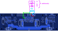
I used a 1W 2.2Ohm resistor. Additionally, due to safety reasons, sangram mentioned to add the violet parts as well. The diodes should be around 6-10A, 600V (in my case as I use 1.25A slow fuses for my amp), the capacitor 20-100nF (ideally X-type).
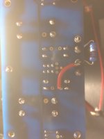
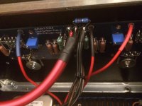
Here you can see (at the moment I did not add the additional components as this was the testing scenario...) the added connection on the backside of my PCB and the HBR
Finally to remove all misunderstandings also a schematic.
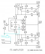
So, the amp is now really really quiet. I have to admit, when my ear is about 2cm (about 0.78 inches
 ) close to the speaker I can still hear some hum, but I think thats the price you have to pay when you build a stereo amp... (maybe a little bit bigger resistor would even kill the rest of it??)
For the background, also the article of David Joffe: http://www.updatemydynaco.com/documents/GroundingProblemsRev1p4.pdf
Thanks one more, all the best,
Philip
some tags for the thread search:
HBRR, HBRL, hum break, hum breaking resistor, chross channel, ground loop, hum, buzz, david joffe
So I finally were able to reduce (nearly cancel) my hum. Many many (many many) thanks at this point to sangram who gave me the final hint, thus told me what I have done wrong so far and helped me with some other questions!
Also many thanks to Andrew and all the other members who tried to help me. As suggested by all I had a cross channel ground loop due to the two connections with the preamp. I think many other builders will get to this point, so I just want to tell what I have done, maybe even in some future this will be added to the PCB...
In post 15283 and 15290 i tried to figure out where to put the hum breaking resistor (HBR) but, this was the wrong position, i should have chosen version A..
So here are the modifications now on my PCB:
The red lines are cut traces. I added the green connection and soldered the blue resistor.

I used a 1W 2.2Ohm resistor. Additionally, due to safety reasons, sangram mentioned to add the violet parts as well. The diodes should be around 6-10A, 600V (in my case as I use 1.25A slow fuses for my amp), the capacitor 20-100nF (ideally X-type).
Here you can see (at the moment I did not add the additional components as this was the testing scenario...) the added connection on the backside of my PCB and the HBR


Finally to remove all misunderstandings also a schematic.

So, the amp is now really really quiet. I have to admit, when my ear is about 2cm (about 0.78 inches
For the background, also the article of David Joffe: http://www.updatemydynaco.com/documents/GroundingProblemsRev1p4.pdf
Thanks one more, all the best,
Philip
some tags for the thread search:
HBRR, HBRL, hum break, hum breaking resistor, chross channel, ground loop, hum, buzz, david joffe
It is such a pity that this happens and gets repeated. One can see in the schematic that it will not work properly when used in a multi-channel amplifier.
One can see how to do it properly in other Forum schematics, yet here we have a DIYaudio Forum sch that gets it wrong.
The HBRR+HBRL solution costs a bit of board space, and a few cheap components. It can be omitted when a mono-block is being implemented.
Why after so many years, do so many still produce incorrect schematics without a warning that they only apply to mono-block?
Last edited:
Daniel Joffe (D.Joffe)
hups,.. sry,...
Just a thought:
The F5 design lends itself greatly as a beginners build. That's why I guess a lot of simple mistakes end up in this thread.
I suggest people in know update the build instructions? If it's that obvious that these mistakes keep being made.
The age old engineering mistaken assumption: Inside out, versus outside in thinking..
Last edited:
Just a thought:
The F5 design lends itself greatly as a beginners build. That's why I guess a lot of simple mistakes end up in this thread.
I suggest people in know update the build instructions? If it's that obvious that these mistakes keep being made.
The age old engineering mistaken assumption: Inside out, versus outside in thinking..
I believe that Mr 6L6 does the build guides almost as a labour of love and I presume is not paid!


Updating them is a lot of work and additions / changes almost get lost in many following pages.
Hey!
So yesterday I also soldered the last missing parts (diodes and capacitor) and had a short listening session (it was already quite late...). So I just have a question concerning the sounding of the amp (I know, a hard topic).
I use an Audiolab DAC and a DCB1 preamp and I listened to some different stuff, coldplay in quite good flac quality really sounded totally clear, holy


Then I tried a song via spotify premium, thus at 320kbps (I know, still shitty quality, but yes...). I don't know what to say, but the voice really sounded dull, not clear at all. Furthermore I recognized suddenly a lot of echo in the song
Then I compared it with my symasym. First I realized, there IS some echo in this song, I just did not hear it that good before , but the voice, compared to the F5, was a little bit "better", not so dull I would say?
Now, whats my question? Did some one had the same experience? Is the F5 just that much better that I now "hear" the bad recordings even more, thus it just sounds not good, or is there something wrong with the amp?
So yesterday I also soldered the last missing parts (diodes and capacitor) and had a short listening session (it was already quite late...). So I just have a question concerning the sounding of the amp (I know, a hard topic).
I use an Audiolab DAC and a DCB1 preamp and I listened to some different stuff, coldplay in quite good flac quality really sounded totally clear, holy


Then I tried a song via spotify premium, thus at 320kbps (I know, still shitty quality, but yes...). I don't know what to say, but the voice really sounded dull, not clear at all. Furthermore I recognized suddenly a lot of echo in the song
Then I compared it with my symasym. First I realized, there IS some echo in this song, I just did not hear it that good before
Now, whats my question? Did some one had the same experience? Is the F5 just that much better that I now "hear" the bad recordings even more, thus it just sounds not good, or is there something wrong with the amp?
- Home
- Amplifiers
- Pass Labs
- F5 power amplifier
