Yes, they're NTC's from Vishay BC Components 4.7k 5% tolerance.
Datasheet is here:
http://cdn-reichelt.de/documents/datenblatt/B400/NTC-02_Serie.pdf
Which thermistors are known to work?
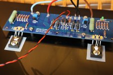
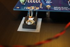
I took some pictures today. They're attatched to this massage.
I tested to reduce the bias to 1A, but it's just the same...
Datasheet is here:
http://cdn-reichelt.de/documents/datenblatt/B400/NTC-02_Serie.pdf
Which thermistors are known to work?
I took some pictures today. They're attatched to this massage.
I tested to reduce the bias to 1A, but it's just the same...
Attachments
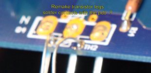
Hi Skroiss....but it's just the same...
Maybe verify and remake if need all solder contacts
")
6L6 build guide are the best to see solder quality work.
Greetings
Attachments
NTCs looks fine ....
what Idss are JFets , and where you bought them ?
what's measured resistance across NTCs , cold , in situ (on pcb) ?
JFETs are selected to ~6mA. I bought them from an germen distributor (Reichelt Elektronik) years ago. 6mA because I got only 2SK170 BL and 2SJ74 GR. I selected them to ~6mA (P-channel is 5.8mA and N-channel is 6.8mA). But close selection should'nt be necessary in this application.
NTC's resistance in situ is ~1.6k Ohm ... Is it in the expected range?
Hi Skroiss
Maybe verify and remake if need all solder contacts
6L6 build guide are the best to see solder quality work.
Greetings
Hi soundhappy,
I learned how to solder professionally. Soldering does'nt look beautiful on the Mos-Fets, but all solder contacts are fine (on the whole board). I drilled the heatsinks against the UMS and the Siliconix IRFP240/IRFP9240 seams to have shorter lags. Therefore creativity was needed
JFETs are selected to ~6mA. I bought them from an germen distributor (Reichelt Elektronik) years ago. 6mA because I got only 2SK170 BL and 2SJ74 GR. I selected them to ~6mA (P-channel is 5.8mA and N-channel is 6.8mA). But close selection should'nt be necessary in this application.
NTC's resistance in situ is ~1.6k Ohm ... Is it in the expected range?
1K6 looks too much , with JFets current in range of 5-6mA
1K6x6mA - that gives 9V of initial voltage
even with just 5mA , that's 8V at hand , to brutally open output mosfets
what combo of trimpot-fixed resistors you have there ?
Has anyone increased the gain of their F5 as described in the F5-T article?
To quote Papa: "You may also notice that the feedback resistors R7 through R10 have been increased, increasing the amplifier's gain to about 22 dB and decreasing the amount of feedback by about 7 dB. If we are going to put out more power it is appropriate to have some more gain, and it gives us more margin for feedback stability – the amplifier still is flat to about 800 Khz. Of course we have noted that the 100 ohm resistors will start to cook at the higher power levels, so we would be making some changes to them anyway."
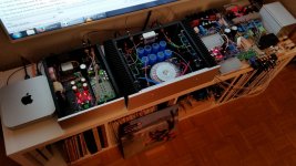
I'm asking because right now the only stages with gain in my system are the power amplifiers. I'm actively bi-amping my speakers with an F5 for the woofers and a Mini Aleph (20dB gain) for the tweeters. I'm currently attenuating the signal going to the tweeter amp quite a bit and feel like I'd need a little more signal to fully drive the F5. With a little more gain in the F5 I think I could get away without an additional gain stage in the line level circuitry.
What are the drawbacks, and how does the mod affect the F5's sound?
Edit: Bonus system pic:
To quote Papa: "You may also notice that the feedback resistors R7 through R10 have been increased, increasing the amplifier's gain to about 22 dB and decreasing the amount of feedback by about 7 dB. If we are going to put out more power it is appropriate to have some more gain, and it gives us more margin for feedback stability – the amplifier still is flat to about 800 Khz. Of course we have noted that the 100 ohm resistors will start to cook at the higher power levels, so we would be making some changes to them anyway."
I'm asking because right now the only stages with gain in my system are the power amplifiers. I'm actively bi-amping my speakers with an F5 for the woofers and a Mini Aleph (20dB gain) for the tweeters. I'm currently attenuating the signal going to the tweeter amp quite a bit and feel like I'd need a little more signal to fully drive the F5. With a little more gain in the F5 I think I could get away without an additional gain stage in the line level circuitry.
What are the drawbacks, and how does the mod affect the F5's sound?
Edit: Bonus system pic:
Attachments
Last edited:
1K6 looks too much , with JFets current in range of 5-6mA
1K6x6mA - that gives 9V of initial voltage
even with just 5mA , that's 8V at hand , to brutally open output mosfets
what combo of trimpot-fixed resistors you have there ?
That's a good hint!!!
1.6k is in situ at the Thermistors. To calculate the Vgs of Power-Fets in cold state, is'nt it more the resistance between jfet drain to voltage rail? This resistance is in situ ~200-210 Ohm in cold state. Measured across the fixed resistor and trim. pot. That gives at 6mA just 1.26V Vgs....
My combo is 2.2k fixed and 5k trimpot.
I have some time tomorrow afternoon to make some more measurements - Vgs cold-hot comparsion and swaping resistors. I hoping, that I find somthing.
Thank you for helping, it is very constructive and is helping me a lot!!!
what I really meant ( and forgot that NTCs are in series with fixed resistors ) is to measure exactly resistance on JFet drains to rail , so group of all these series paralleled thingies
be sure what you have there , if you have significant difference in measurements with swapped probes , desolder bjts and JFets and measure again
1V26 is certainly too low to explain/result in massive current surge
be sure what you have there , if you have significant difference in measurements with swapped probes , desolder bjts and JFets and measure again
1V26 is certainly too low to explain/result in massive current surge
what I really meant ( and forgot that NTCs are in series with fixed resistors ) is to measure exactly resistance on JFet drains to rail , so group of all these series paralleled thingies
be sure what you have there , if you have significant difference in measurements with swapped probes , desolder bjts and JFets and measure again
1V26 is certainly too low to explain/result in massive current surge
Yesterday I thinked about the resistor circuit that is forming the Vgs voltage for the MOS-FETs and what influence it would have if JFET current ist just 6mA instead of 10mA. Resistence must be about 50% higher to get the same Vgs voltage. If I adjust that only atn the trimpots, the ratio of thermistor portion to resistor/trimpot portion is altered. The termistor has more infuence. O.k. I swapt the 2k2 in series to NTC against 3k3. This should reduce ratio of the thermistor circuit.
That brought a improvement and a new finding:
The inprovement is, that thecurrent drain is now only for a fraction of a second. To fast away to see on a DMM. I just hear the humm from the switching regulators.
And the findig ist, that the issue is just present if I have connected my pre-stage to the F5. My pre is just a passive volume pot (10k)!!! It does'nt matter in which position the pot is.
Is the F5 prone to capacitive loads on the input? I'm asking because I'm using twisted pairs for small signal wiring. They might have higher capacity than usual coax cables....
I need to take some plots with the scope to see if the F5 is oszilating in the startup current drain situation.
- Home
- Amplifiers
- Pass Labs
- F5 power amplifier