Hi Halair,
I just noticed your photo of your wiring scheme on post 14,936 (23/6) and am a bit puzzled about the coloured lines detailing the layout of the power supply - is this the way you intend to wire it up or is this how you've done it? - let's see if I understand the layout correctly ...
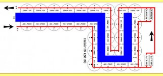
If I understand your blue and yellow lines, the block bridge on the left hand side connects to 15 // capacitors, then presumably thru a resistor (with the 2 // axial caps?) and then thru another 15 // caps to feed both channels the -ve voltage power, yes? and the same ly for the +ve rail?
The supply connections from these supply assemblies is passed directly behind the transformer and over the top of those 'noisy' block bridges, on their way to deliver current to the amp pcbs, yes?
And the '0 Volt' wire from the amps pcbs is twisted with these supply wires and then passed directly over these block bridges and transformer on their way to the central '0 Volt' point then onto the 'ground lift' thermistor, yes?
And the SPKR return wire is twisted around the SPKR+ wire and continued on to the central '0 Volt' point, yes?
I'm surprised that Andrew hasn't commented on this before but here goes for my opinion ...
First, I dislike GB block bridges in amp power supplies and especially in the F5 design, but that's just me - there are some Schottky ones available that are okay - my opinion here, plenty of other people have no problems with them.
Second, this string of capacitors in each bank for each channel has created it's own series resistance (like multiple parallel R - C networks), and the 'best filtering' is at the far end of these banks (where you've added those 2 // Phillips caps) and this is the point where you connect the wires to the power amp pcbs and take them directly across, not looped them around the transformer, block bridges, etc - twisted together as you've indicated - not anywhere near those extremely noisy block bridges - more about this below
This will take all your supply wiring away from both the transformer and the diodes.
I would suggest you change the wiring - rewire your capacitot assemblies so you have the +ve and -ve rails on each assembly - although this halves the capacitor total value, the benefits are shorter wires, separate supplies/channel, bigger distances between diodes, transformers, etc etc
Some people say that you should attach the power supply ground wire at the bridges and sometimes good results can be achieved this way, but not often - it's easy to try either way anyway, just to satisfy curiosity.
What's next - well, another controversial one - speaker return wire - directly to central '0 Volt' point between caps on supply or at the amps pcb twisted rogether with the SPKR + wire
Some people insist that it should go directly to the central '0 Volt' points at all times as most direct current loop connection - pretty established method
But- on the official FirstWatt amps, the return wire is taken to the amp pcb and then all the amps ground connections is then connected to the central '0 Volt' point with another separate wire - 2 'star earth' connection, as they say.
I've found that either gives good results but again, easy to try both methods in your own build.
That's about it except I'd seriously suggest a dc protection module and some of the cheap ones are quite okay - most negative comments are about the reliability and contact materials of the relays but can use power fets instead, if concerned about this
A mains 'dc trap' is a must if the power transformer is over 300va (in my opinion, again, I add) - they're simple things, cost very little and in some bad mains situations can provide enormous improvements in the sound of the amp
All the best
I just noticed your photo of your wiring scheme on post 14,936 (23/6) and am a bit puzzled about the coloured lines detailing the layout of the power supply - is this the way you intend to wire it up or is this how you've done it? - let's see if I understand the layout correctly ...
If I understand your blue and yellow lines, the block bridge on the left hand side connects to 15 // capacitors, then presumably thru a resistor (with the 2 // axial caps?) and then thru another 15 // caps to feed both channels the -ve voltage power, yes? and the same ly for the +ve rail?
The supply connections from these supply assemblies is passed directly behind the transformer and over the top of those 'noisy' block bridges, on their way to deliver current to the amp pcbs, yes?
And the '0 Volt' wire from the amps pcbs is twisted with these supply wires and then passed directly over these block bridges and transformer on their way to the central '0 Volt' point then onto the 'ground lift' thermistor, yes?
And the SPKR return wire is twisted around the SPKR+ wire and continued on to the central '0 Volt' point, yes?
I'm surprised that Andrew hasn't commented on this before but here goes for my opinion ...
First, I dislike GB block bridges in amp power supplies and especially in the F5 design, but that's just me - there are some Schottky ones available that are okay - my opinion here, plenty of other people have no problems with them.
Second, this string of capacitors in each bank for each channel has created it's own series resistance (like multiple parallel R - C networks), and the 'best filtering' is at the far end of these banks (where you've added those 2 // Phillips caps) and this is the point where you connect the wires to the power amp pcbs and take them directly across, not looped them around the transformer, block bridges, etc - twisted together as you've indicated - not anywhere near those extremely noisy block bridges - more about this below
This will take all your supply wiring away from both the transformer and the diodes.
I would suggest you change the wiring - rewire your capacitot assemblies so you have the +ve and -ve rails on each assembly - although this halves the capacitor total value, the benefits are shorter wires, separate supplies/channel, bigger distances between diodes, transformers, etc etc
Some people say that you should attach the power supply ground wire at the bridges and sometimes good results can be achieved this way, but not often - it's easy to try either way anyway, just to satisfy curiosity.
What's next - well, another controversial one - speaker return wire - directly to central '0 Volt' point between caps on supply or at the amps pcb twisted rogether with the SPKR + wire
Some people insist that it should go directly to the central '0 Volt' points at all times as most direct current loop connection - pretty established method
But- on the official FirstWatt amps, the return wire is taken to the amp pcb and then all the amps ground connections is then connected to the central '0 Volt' point with another separate wire - 2 'star earth' connection, as they say.
I've found that either gives good results but again, easy to try both methods in your own build.
That's about it except I'd seriously suggest a dc protection module and some of the cheap ones are quite okay - most negative comments are about the reliability and contact materials of the relays but can use power fets instead, if concerned about this
A mains 'dc trap' is a must if the power transformer is over 300va (in my opinion, again, I add) - they're simple things, cost very little and in some bad mains situations can provide enormous improvements in the sound of the amp
All the best
So U got Expensive fuses wlong way round but bulb did not go dim
Bulb did not go dim because it draw no currants (as in AMPs Like)
Put them back right way and try again after all U don't say U blow smoke and such so...
Just measure up those trimmers for starter
Next time try whit power supply wlong way round much funnier
Thank you for your reply Bksabath
Done your suggestion. Biased up ok, now giving the a long soak.
Hi all,
I am reading back through this thread but I want to be sure. Is the BOM that is linked on the build guide page current for v3 of the circuit boards? I am ready to begin stuffing but I don't want to make any mistakes...I was looking at R9 and R10 and they call for 1/4w resistors but the spots on the boards look bigger...thanks
I am reading back through this thread but I want to be sure. Is the BOM that is linked on the build guide page current for v3 of the circuit boards? I am ready to begin stuffing but I don't want to make any mistakes...I was looking at R9 and R10 and they call for 1/4w resistors but the spots on the boards look bigger...thanks
Hi all,
I am reading back through this thread but I want to be sure. Is the BOM that is linked on the build guide page current for v3 of the circuit boards? I am ready to begin stuffing but I don't want to make any mistakes...I was looking at R9 and R10 and they call for 1/4w resistors but the spots on the boards look bigger...thanks
I have found this BOM for v3. Is this correct? Thanks
Attachments
Thank you for your reply Bksabath
Done your suggestion. Biased up ok, now giving the a long soak.
You most welcome
Enjoy
Papa amps are way beterer than rest.
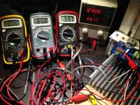
Mmmm... quick first F5 board test")
Just a word of warning, I own the same Velleman version in the middle, it's readings are often off by about 10%, compared to my fluke and Osciloscope..
Just a word of warning, I own the same Velleman version in the middle, it's readings are often off by about 10%, compared to my fluke and Osciloscope..
@ Stijn001
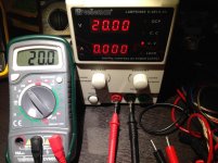
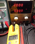
I have verified all multimeters and bench psu calibration with Fluke
after your message and it's the same voltage value on all windows.
Thanks for council and best regards
Just a word of warning, I own the same Velleman version in the middle,
it's readings are often off by about 10%, compared to my fluke and Osciloscope..
Probably internal battery discharge in yours ?
Agilent , HP or other 000 $ very high precision
lab multimeters not this time
For bias and offset is just ok
Best regards
Attachments
Probably internal battery discharge in yours ?
I have two identical DMM's where one is low on power, it will read incorrectly 0,9V while the fully powered DMM give the expected reading of 0,6V. (A third DMM verify 0,6V as correct value)
Hi Halair,
I just noticed your photo of your wiring scheme on post 14,936 (23/6) and am a bit puzzled about the coloured lines detailing the layout of the power supply.
1 - is this the way you intend to wire it up or is this how you've done it? - let's see if I understand the layout correctly ...
If I understand your blue and yellow lines, the block bridge on the left hand side connects to 15 // capacitors, then presumably thru a resistor (with the 2 // axial caps?) and then thru another 15 // caps to feed both channels the -ve voltage power, yes? and the same ly for the +ve rail?
2 - The supply connections from these supply assemblies is passed directly behind the transformer and over the top of those 'noisy' block bridges, on their way to deliver current to the amp pcbs, yes?
And the '0 Volt' wire from the amps pcbs is twisted with these supply wires and then passed directly over these block bridges and transformer on their way to the central '0 Volt' point then onto the 'ground lift' thermistor, yes?
3 - And the SPKR return wire is twisted around the SPKR+ wire and continued on to the central '0 Volt' point, yes?
I'm surprised that Andrew hasn't commented on this before but here goes for my opinion ...
First, I dislike GB block bridges in amp power supplies and especially in the F5 design, but that's just me - there are some Schottky ones available that are okay - my opinion here, plenty of other people have no problems with them.
Second, this string of capacitors in each bank for each channel has created it's own series resistance (like multiple parallel R - C networks), and the 'best filtering' is at the far end of these banks (where you've added those 2 // Phillips caps) and this is the point where you connect the wires to the power amp pcbs and take them directly across, not looped them around the transformer, block bridges, etc - twisted together as you've indicated - not anywhere near those extremely noisy block bridges - more about this below
This will take all your supply wiring away from both the transformer and the diodes.
I would suggest you change the wiring - rewire your capacitot assemblies so you have the +ve and -ve rails on each assembly - although this halves the capacitor total value, the benefits are shorter wires, separate supplies/channel, bigger distances between diodes, transformers, etc etc
Some people say that you should attach the power supply ground wire at the bridges and sometimes good results can be achieved this way, but not often - it's easy to try either way anyway, just to satisfy curiosity.
What's next - well, another controversial one - speaker return wire - directly to central '0 Volt' point between caps on supply or at the amps pcb twisted rogether with the SPKR + wire
Some people insist that it should go directly to the central '0 Volt' points at all times as most direct current loop connection - pretty established method
But- on the official FirstWatt amps, the return wire is taken to the amp pcb and then all the amps ground connections is then connected to the central '0 Volt' point with another separate wire - 2 'star earth' connection, as they say.
I've found that either gives good results but again, easy to try both methods in your own build.
Hi and again thanks for adding in
1 - The drawing you refer to show the actual wiring layout as it is today.
I have also added a drawing showing the actual layout of the positive power rail.
Good point regarding power line running in close proximity with the bridge rectifiers, I was not aware of the possible issue but it makes sense. Will investigate as time allows it.
2 - Yes
3 - Yes, but I did add a jumper from speaker negative terminal directly to star ground and the level of hum was reduced.
On my test speaker (84db sensitivity) there is no audible hum detectable with ear next to driver, on a different system with a high-80 sensitivity level there it barely audible hum (not audible at listening position 2m away) and with my Line arrays in the high 90's I can hear hum from listening position at 3m distance. It is not detectable when playing music but its present.
My F5 have been powered ON for the past weeks and bias was retested and found to be fine so it appear to be working beautifully. What remain now is to eliminate the hum/optimizing the internal wiring.
Testing with ground jumpers is easy enough
Attachments
I have three battery powered DMM, all fairly cheap.I have two identical DMM's where one is low on power, it will read incorrectly 0,9V while the fully powered DMM give the expected reading of 0,6V. (A third DMM verify 0,6V as correct value)
All have a battery warning symbol.
The two older DMM still read pretty accurately soon after the battery starts to show as low.
The new one has not run out of battery yet, so I don't know if it becomes inaccurate as battery goes low.
F5 Power Amplifier photos
I wanted to share results of my F5 Power Amplifier build so attached are photos. I was very pleased with the sound and power of the amplifier. Using a 1.3A bias current the temperature rise over room ambient is 18'C (64'F). For more information and photos please see my website, www.soundsperfectstudio.com, from the menu choose the DIY Audio Projects page, the rest of the website is devoted to guitar teaching. This was not my first amplifier build, future plans include constructing a F5 Turbo Power Amplifier. Many thanks to DIY Audio and Nelson Pass for the opportunity to construct this great amplifier.
I wanted to share results of my F5 Power Amplifier build so attached are photos. I was very pleased with the sound and power of the amplifier. Using a 1.3A bias current the temperature rise over room ambient is 18'C (64'F). For more information and photos please see my website, www.soundsperfectstudio.com, from the menu choose the DIY Audio Projects page, the rest of the website is devoted to guitar teaching. This was not my first amplifier build, future plans include constructing a F5 Turbo Power Amplifier. Many thanks to DIY Audio and Nelson Pass for the opportunity to construct this great amplifier.
An externally hosted image should be here but it was not working when we last tested it.
@sohryuab
r35 is 33.2k
or see ->http://www.diyaudio.com/forums/diyaudio-store/227933-diyaudio-f5-build-guide.html
r35 is 33.2k
or see ->http://www.diyaudio.com/forums/diyaudio-store/227933-diyaudio-f5-build-guide.html
- Home
- Amplifiers
- Pass Labs
- F5 power amplifier