Hi Russel.
The cold board had full voltage available at V(+) and V(-) inputs.
The SK170 used came from ebay-user "altweit" in Israel, afaik he can provide genuine jfets but I cannot verify. (I knew that prior to purchase)
The amp did biad properly and in the expexted manner with an easily controllable offset, yet apparently went dead some time during warm-up. In this state I could somewhat manipulate offset but it fluctuates a bit and will not settle in at 0. The second amp was cooking steadily during all this.
Last edited:
This seems to be a recurring problem that is being reported by a few Member Builders.
It starts and biases up correctly first time. But after a cool down and restart something goes wrong.
Some are unlucky in that the restart damages some component.
If it is the restart that trigger these events, what measures can be done to the circuit to reduce/eliminate this from happening?
In my case I have a single CL60 in series with primary, and a X1 cap across the switch in case this can have impact on the situation. (400VA PSU, 2x66.000uF bank)
Also, when I left the amp to cook both sides biased nicely so both amps was ok when left aside.
Last edited:
I don't know why the F5 damages itself on next restart.
Could it be down to a lack of input RF attenuation? Or an over-voltage incident on one device during the start up, when voltages are changing very quickly, i.e. a dv/dt problem?
As far as input RF attenuation my RCA inputs have been kept open. Coax cable used between RCA/PCB inputs. I have seen others suggest shorted inputs (RCA) during biasing?
Over voltage or dv/dt issue - no means to check that from my end (lack of knowledge I am afraid)
The only voltage the PCB should see is from the cap bank and this capacity should spend some cycles before voltage is up... Perhaps if inline resistanse of PSU is insufficient the ripple voltage at start-up could make for a harsher enviroment?
You must short the inputs during biasing and leave the output open.
But with a DC coupled amplifier this can result in a problem when finally connected to a source that has an output offset that is not exactly zero uVdc.
The F5 also has a completely open output, Pass has not shown, nor recommended, a Thiele Network, not even just an Output Zobel. Could there be a momentary instability as the voltages change, that damages a component?
Last edited:
Hi Russel.
The cold board had full voltage available at V(+) and V(-) inputs.
The SK170 used came from ebay-user "altweit" in Israel, afaik he can provide genuine jfets but I cannot verify. (I knew that prior to purchase)
The amp did biad properly and in the expexted manner with an easily controllable offset, yet apparently went dead some time during warm-up. In this state I could somewhat manipulate offset but it fluctuates a bit and will not settle in at 0. The second amp was cooking steadily during all this.
I have always heard he was a very reliable source. Very odd these problems. If you are getting voltage, something is failing on the board. I can see once, but isn't this twice for this channel? Remind me is this a stereo amp with one power supply, a dual mono with 2, or are they mono blocks? If you test the J-fets, it is still puzzling. If they survived, what happened? If they are now dead, why?
Russellc
Last edited:
I built mine some time ago. I fired it up with nothing on outputs or inputs, I have since learned to short inputs. I had no trouble, but I used a variac when I fired it up.
Andrew may be on to something, back when I built mine I don't remember this being so common....either it fired up, or failed, usually because of a construction error, reversed j fet or what ever
Russellc
Andrew may be on to something, back when I built mine I don't remember this being so common....either it fired up, or failed, usually because of a construction error, reversed j fet or what ever
Russellc
The good amp have had zero issues, its the same side that now have failed twice.
I'll pull out the SK170/J74 and test them individually, they are mounted correctly - that has been verified. And each resistor match the resistors of the good side, they were also matched to each other prior to be solder/PCB.
Mine is built as a stereo amp with one toroid.
I'll pull out the SK170/J74 and test them individually, they are mounted correctly - that has been verified. And each resistor match the resistors of the good side, they were also matched to each other prior to be solder/PCB.
Mine is built as a stereo amp with one toroid.
Last edited:
The good amp have had zero issues, its the same side that now have failed twice.
I'll pull out the SK170/J74 and test them individually, they are mounted correctly - that has been verified. And each resistor match the resistors of the good side, they were also matched to each other prior to be solder/PCB.
Mine is built as a stereo amp with one toroid.
All I can suggest is a new board and rebuild from new parts, as long as the power supply is measuring correctly on that side, likely it is. Seems like problem is narrowed to that board or some part on it, defect, solder bridge or something...very odd.
Russellc
Andrew may be on to something, back when I built mine I don't remember this being so common
If it's any help, I have built a couple hundred of these, and never run into that.

If it's any help, I have built a couple hundred of these, and never run into that.
Other than error on that particular board, any suggestions? All mine fired up fine, but that's only 2! Is there something other than error on that board, whether defective part or whatever that would cause this? His other channel is reported to be fine...thats about the end of my limited analytical ability here...What is your fire up protocol? Variac?
Russellc
Last edited:
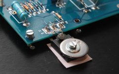
Could this problem be due to bad / discontinuous thermal contact of the thermistor(s) with the mosfet after the first thermal cycle?
Beyond my knowledge, but I know many build without those thermistors and safety circuit altogether without problem...unless there outputs get shorted! I've always included them myself...
Russellc
Long story short:
First time both sides biased easily enough, both sides played music. Both channels went suddenly pop as in immediate change from playing music to outputting a strong hum. Not super loud or anything but far from modest. This hum would be present with only the F5 connected, no inputs or anything (it was quiet prior)
Both Q1 (2SK170) was toast, no other damaged components found.
Second time, both channels repopulated with new and genuine Q1-Q6 using Harris IRFP´s for Q3-4.
First channel biased nicely, second was troublesome and at one stage R3 smoked and Q1 was confirmed dead during autopsy. Both played music prior (ruling out wrong placement of parts)
3rd time, dead channel repaired with new R3 and Q1. Intial bias went smoothly and numbers were fine, brought up to same bias level as the good side.
Good side was reconnected (have always biased the amps individually)
Both amps fired up fine, bias identical (0.575V) with offset=0 over both outputs
Previous bad amp was now cold after left to cook for an hr, bias read=0 and offset 0,030-something mV, and fluctuating +/- 25 or so mV.
Thermistors (TH) are in place and in direct contact with the mosfets.
At start-up the offset register about 20mV off before settling in at 0 briefly afterwards.
Both negative speaker outputs share connection to chassis GND with a CL60 in series. Both negative terminals are connected to Audio GND1. Audio GND2 is connected to rectifier.
Could the DC off the cap bank be insufficiently stable/excessive ripple? I use CRC as per Pass schematic. At no load the PSU provide +/-26,2V and with one amp running its down to 49,something measured over the V+/V- input.
I do not expect "you" to fix this, I hope to be able to sort this out and learn more in the process. But I am on the deep end as far as know-how is concerned so any input/thoughts are appreciated
Next step at my end is to remove Q1 and test it. In parallel I will probably start fresh with a new board/new components.
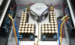
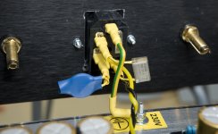
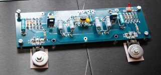
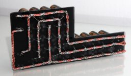
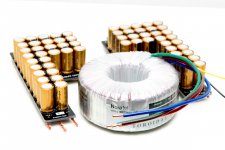
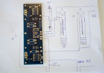
Pic of build found below.
First time both sides biased easily enough, both sides played music. Both channels went suddenly pop as in immediate change from playing music to outputting a strong hum. Not super loud or anything but far from modest. This hum would be present with only the F5 connected, no inputs or anything (it was quiet prior)
Both Q1 (2SK170) was toast, no other damaged components found.
Second time, both channels repopulated with new and genuine Q1-Q6 using Harris IRFP´s for Q3-4.
First channel biased nicely, second was troublesome and at one stage R3 smoked and Q1 was confirmed dead during autopsy. Both played music prior (ruling out wrong placement of parts)
3rd time, dead channel repaired with new R3 and Q1. Intial bias went smoothly and numbers were fine, brought up to same bias level as the good side.
Good side was reconnected (have always biased the amps individually)
Both amps fired up fine, bias identical (0.575V) with offset=0 over both outputs
Previous bad amp was now cold after left to cook for an hr, bias read=0 and offset 0,030-something mV, and fluctuating +/- 25 or so mV.
Thermistors (TH) are in place and in direct contact with the mosfets.
At start-up the offset register about 20mV off before settling in at 0 briefly afterwards.
Both negative speaker outputs share connection to chassis GND with a CL60 in series. Both negative terminals are connected to Audio GND1. Audio GND2 is connected to rectifier.
Could the DC off the cap bank be insufficiently stable/excessive ripple? I use CRC as per Pass schematic. At no load the PSU provide +/-26,2V and with one amp running its down to 49,something measured over the V+/V- input.
I do not expect "you" to fix this, I hope to be able to sort this out and learn more in the process. But I am on the deep end as far as know-how is concerned so any input/thoughts are appreciated
Next step at my end is to remove Q1 and test it. In parallel I will probably start fresh with a new board/new components.
Pic of build found below.
Attachments
Last edited:
.....
Both negative speaker outputs share connection to chassis GND with a CL60 in series. Both negative terminals are connected to Audio GND1. Audio GND2 is connected to rectifier......
clarify
Can you measure the Vgs on the output MOSFET on the good and bad channels? This should tell you whether the problem is at the input or the output.
Also see if temporarily disabling the current limiting helps.
If I was you I would bias it to about half the recommend bias for a day or so before giving it full beans. I normally do that to verify that the circuit is OK. I use even less, just 150mA for a couple days at least.
Also see if temporarily disabling the current limiting helps.
If I was you I would bias it to about half the recommend bias for a day or so before giving it full beans. I normally do that to verify that the circuit is OK. I use even less, just 150mA for a couple days at least.
clarify
Attachments
Hi there,
I'd like to get less heath from my F5, so I wonder wether it could be underpowered, for instance, by a variac transformer
An alternative would be to rewire my power transformer's inputs so as to half the output voltage. In such condition the power supply rails will have +/-12V instead of +/-24V
Have you tried ? Do you have some comments ? Will the F5 behave properly ?
Many thanks
- Home
- Amplifiers
- Pass Labs
- F5 power amplifier